Anti-condensation motor

A technology of anti-condensation and motor housing, applied in the direction of electrical components, electromechanical devices, electric components, etc., can solve the problems of hidden dangers in motor performance, large installation space, and large space size, so as to ensure relative humidity and pressure, prevent Effect of air convection heat transfer and prevention of contact heat transfer

Inactive Publication Date: 2020-12-29
SUZHOU KAIBO YIKONG DRIVE TECH CO LTD
View PDF8 Cites 0 Cited by
  • Summary
  • Abstract
  • Description
  • Claims
  • Application Information

AI Technical Summary

Problems solved by technology

[0003] The anti-condensation measures that have appeared in the prior art include: 1) By spraying "three-proof" paint inside the junction box, the insulation performance of the motor can be improved, but the probability of condensation cannot be reduced, and the condensation problem has not been fundamentally solved; 2) Adding a desiccant inside the junction box can solve the condensation in a short time, but it needs to be replaced regularly. The replacement needs to remove the box cover, which brings hidden dangers to the performance of the motor and poor maintainability; 3) adding a dehumidification device requires a large installation space. The cost is high, and the reliability of the humidity and temperature sensors inside the device is not high; 4) Adding a heat insulation layer to the junction box cover can reduce the occurrence of condensation on the inner wall of the box cover, but the condensation phenomenon around the junction box cannot be effectively solved
[0004] The existing anti-condensation measure (CN110943568A) is to isolate the winding working cavity and the junction box cavity through the terminal connection assembly. The terminal connection assembly structure is composed of metal terminals, retaining rings, nylon fixing plates, and O-rings. The structure is relatively Complex, many parts, high processing cost, and the metal terminal should not be too large, otherwise the size of the nylon fixing plate will increase exponentially, and the installation space will be relatively large; this structure is more suitable for applications that do not require a high contact area of ​​the metal terminal Small current motors are limited by size and installation space, so the versatility is not strong

Method used


Image

  • Anti-condensation motor
  • Anti-condensation motor
  • Anti-condensation motor

Examples


Embodiment Construction

[0026] The preferred embodiments of the present invention will be described in detail below in conjunction with the accompanying drawings, so that the advantages and features of the present invention can be more easily understood by those skilled in the art, so as to define the protection scope of the patent of the present invention more clearly.

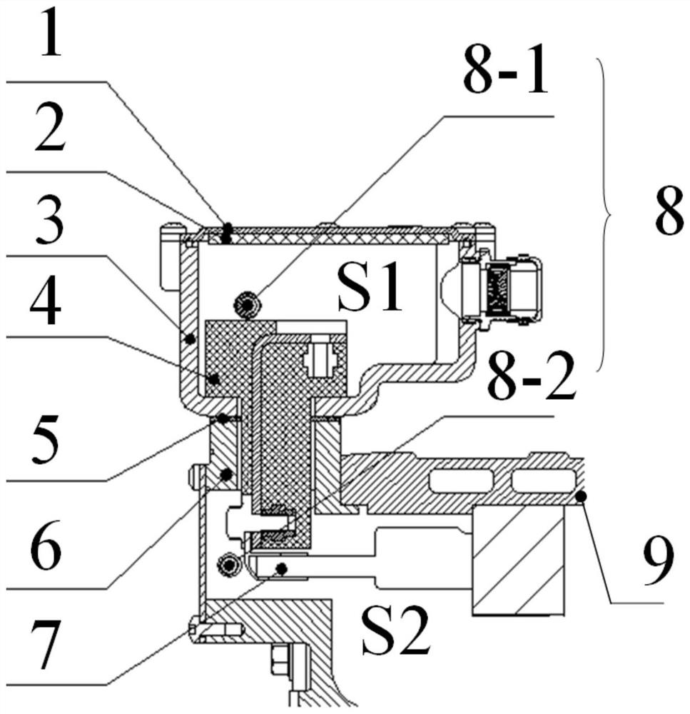
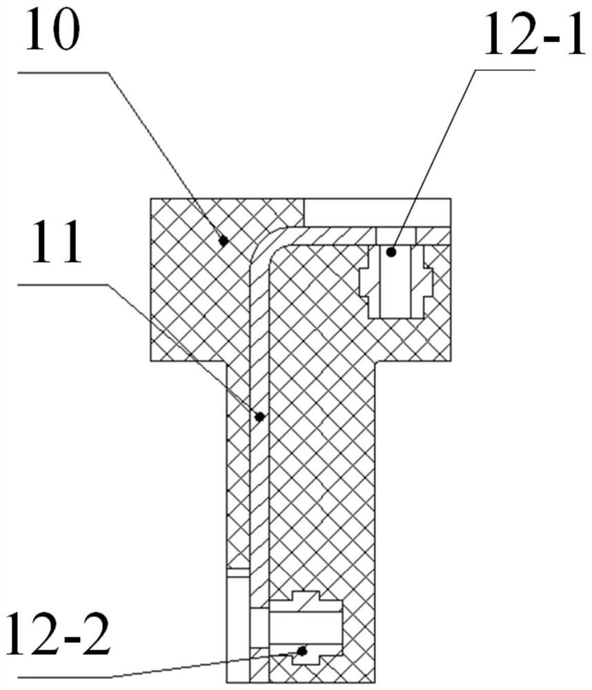
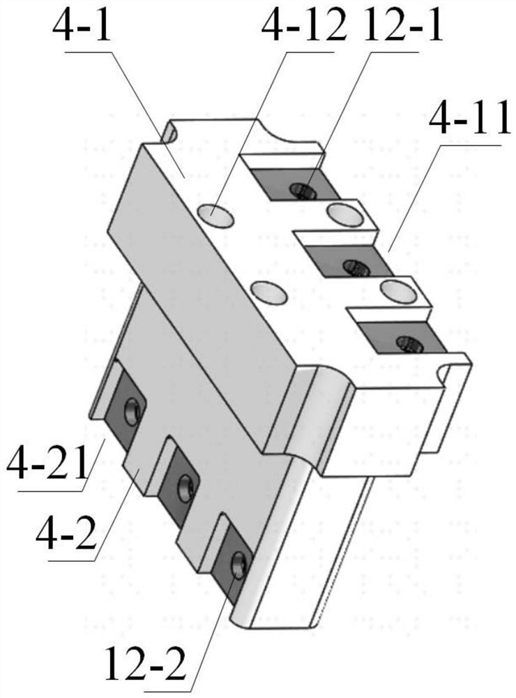
[0027] Such as Figure 1-3 As shown, an anti-condensation motor includes a motor housing. The motor housing includes a motor base 9 and a motor end cover 6 located on one side of the motor base. The junction box 3 is abutted against the motor end cover 6 through the lower end. Connected and installed on the motor casing, the inside of the junction box 3 forms a junction box cavity S1, the inside of the motor casing forms a winding working cavity S2, and a terminal block 4 is arranged between the junction box cavity S1 and the winding working cavity S2 In order to seal and isolate the junction box cavity S1 and the winding working ca...


PUM


Abstract

The invention relates to an anti-condensation motor. A wire holder (4) is arranged between a junction box cavity (S1) and a winding working cavity (S2) so as to seal and isolate a junction box cavity(S1) and the winding working cavity (S2) from each other. The winding working cavity and the junction box cavity are isolated through the wire holder, so that air convection heat transfer between thecavities is prevented. The junction box and an end cover are isolated by a rubber sealing gasket to prevent contact heat transfer. Therefore, a large amount of heat generated by the winding during operation of the motor cannot be transmitted to the junction box cavity, large temperature difference cannot be generated between air in the junction box cavity and the junction box shell, meanwhile, under the action of a breathing plug, the relative humidity and pressure of the winding working cavity and the junction box cavity are guaranteed, and the condensation phenomenon of the motor is effectively prevented.

Description

technical field [0001] The invention relates to the technical field of an anti-condensation structure of a water-cooled motor, in particular to an anti-condensation motor. Background technique [0002] Under the conditions of high humidity and low temperature in the external environment, after the motor stops running, it is easy to condense dew on the inner wall of the junction box cavity, resulting in a decrease in the insulation performance of the motor or even an internal short circuit; condensation falling inside the motor will corrode the internal metal parts of the motor, Seriously affect the performance of the motor, and may even burn the motor. Condensation inside the motor mostly occurs on the inner wall of the junction box shell and inside the box cover. The reason is that the interior of the water-cooled motor can be divided into a winding working cavity and a junction box cavity. Usually, the two are completely connected. When the motor is running, the winding i...

Claims


Application Information

Patent Timeline
Patent Type & Authority Applications(China)
IPC IPC(8): H02K3/50H02K5/22H02K5/10
CPCH02K3/50H02K5/10H02K5/225H02K2205/09
Inventor 郝庆军曹铮赵韶楠陆中华巫文超
Owner SUZHOU KAIBO YIKONG DRIVE TECH CO LTD
Why Eureka
Try Eureka