Noise testing device for speed reducer

A test device, reducer technology, applied in the direction of measuring device, testing of mechanical components, testing of machine/structural components, etc., can solve the problems of inaccurate test results, slow test speed, waste of labor and labor, etc.

Active Publication Date: 2020-04-17
广东馥融传动科技有限公司
View PDF14 Cites 3 Cited by
  • Summary
  • Abstract
  • Description
  • Claims
  • Application Information

AI Technical Summary

Problems solved by technology

[0002] The reducer is the intermediate link in which the power unit drives the actuator. It converts high-speed and low-torque into low-speed and high-torque. It is used in conjunction with the engine. During operation, the reducer will produce a certain amount of noise. If the noise exceeds a certain range, it means that the reducer is faulty. Problem, therefore, after the reducer is assembled, it is necessary to perform noise detection on it. In the prior art: the patent of authorized publication number CN207937158U discloses a reducer noise test platform, which includes a base platform fixed horizontally on the base platform The positioning table of the reducer, the guide column vertically fixed on the rear side of the abutment, the motor mounting plate slidably installed on the guide column, the motor fixed on the motor mounting plate, and the wire that drives the motor mounting plate to slide up and down along the guide column The rod nut assembly needs to be manually tested one by one reducer, the test speed is slow, the efficiency is low, the test requires a lot of people, a waste of manpower and labor, and the test result is inaccurate, so we propose a reducer noise test device address the above deficiencies

Method used


Image

  • Noise testing device for speed reducer
  • Noise testing device for speed reducer
  • Noise testing device for speed reducer

Examples


Embodiment 1

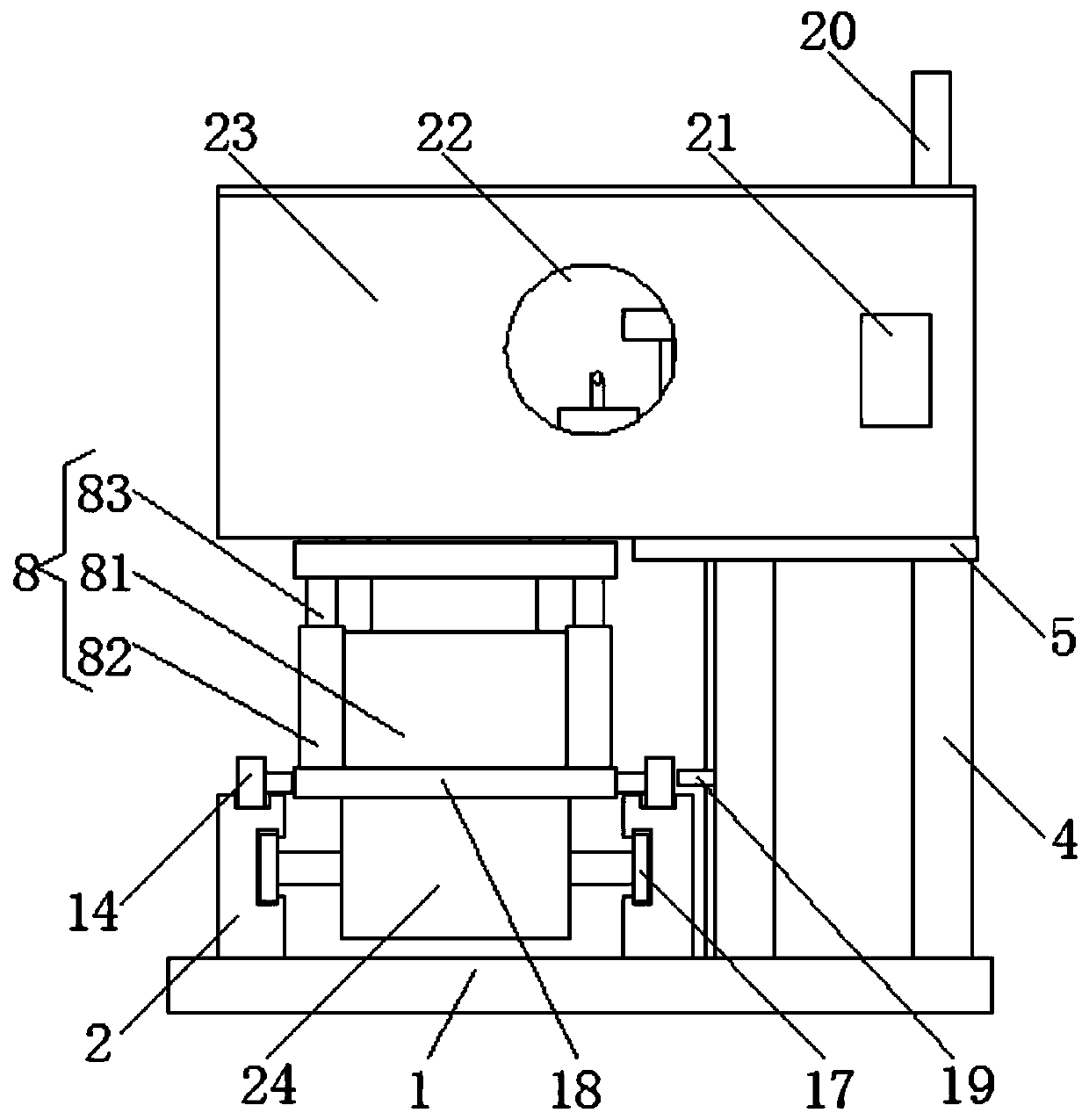
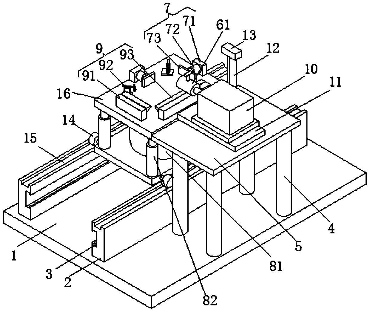
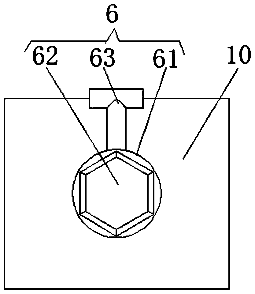
[0021]Embodiment 1: A noise test device for a reducer, including a bottom plate 1, a connecting unit 6, a lifting unit 8, a lifting plate 16 and a biaxial motor 24, and two symmetrically distributed guide rails 2 are arranged on the left side of the upper surface of the bottom plate 1, The inner side of the guide rail 2 is provided with a rack groove 3, and the right end of the upper surface of the bottom plate 1 is provided with four symmetrically distributed legs 4, the upper surfaces of the legs 4 are connected with the lower surface of the table 5, and the upper surface of the table 5 is aligned with the straight line The lower surface of the stator of the motor 11 is fixedly connected, and the upper surface of the mover of the linear motor 11 is fixedly connected with the test motor 10. The connecting unit 6 includes a connecting cylinder 61, a hexagon socket 62 and a locking bolt 63. The right end of the connecting cylinder 61 is connected to the testing motor. The end of...

Embodiment 2

[0024] The difference between this embodiment and Embodiment 1 is:

[0025] In this embodiment, the lifting unit 8 includes a second electric push rod 81, a sleeve 82 and a guide column 83, the lower end of the second electric push rod 81 is fixedly connected with the upper surface of the moving plate 18, and the upper end of the second electric push rod 81 Fixedly connected with the lower surface of the lifting plate 16, the sleeve 82 has four and is symmetrically arranged on the four corners of the upper surface of the moving plate 18, the upper end of the guide column 83 is welded with the lower surface of the lifting plate 16, and the outer arc surface of the guide column 83 is connected to the lower surface of the lifting plate 16. The inner arc surface of the corresponding sleeve 82 is slidingly connected, and the second electric push rod 81 is electrically connected to the PLC controller 21 .

[0026] Specifically, it is set in this way, the second electric push rod 81 ...

Embodiment 3

[0028] The difference between this embodiment and Embodiment 1 is:

[0029] In this embodiment, the positioning unit 7 includes a first support plate 71, a first electric push rod 72 and a push plate 73. There are two first support plates 71 and they are respectively arranged on the left end and the rear end of the upper surface of the lifting plate 16. An electric push rod 72 is fixedly connected to the side of the corresponding first support plate 71 , a push plate 73 is fixedly connected to the end of the corresponding first electric push rod 72 , and the first electric push rod 72 is connected to the PLC controller 21 .

[0030] Specifically, it is set in this way, the reducer is placed on the upper surface of the lifting plate 16, the first electric push rod 72 is opened by the PLC controller 21, the first electric push rod 72 pushes the push plate 73 to move, and the push plate 73 pushes the speed reducer. The movement of the base makes the base of the reducer contact wi...


PUM


Abstract

The invention discloses a noise testing device for a speed reducer. The device comprises a bottom plate, a connecting unit, a lifting unit, a lifting plate and a double-shaft motor, two symmetrically-distributed guide rails are arranged on the left side of the upper surface of the bottom plate. Rack grooves are formed in the inner sides of the guide rails; four supporting legs which are symmetrically distributed are arranged at the right end of the upper surface of the bottom plate; the upper surfaces of the support legs are connected with the lower surface of a bedplate; the upper surface ofthe bedplate is fixedly connected with the lower surface of a stator of the linear motor; the upper surface of a rotor of the linear motor is fixedly connected with a test motor; the connecting unit is arranged at the tail end of the output shaft of the test motor; the end head of the output shaft of a dual shaft motor is fixedly connected with the gear, the gear is connected with the inside of the corresponding rack groove in an engagement way, and a movable plate is fixedly connected on the upper surface of the dual shaft motor. According to the noise testing device for the speed reducer, anassembly line operation mode is adopted, the noise testing device for the speed reducer is high in testing speed, high in efficiency and accurate in testing result, manpower and labor force are saved, and convenience is brought to people.

Description

technical field [0001] The invention relates to the technical field of reducer assembly, in particular to a reducer noise testing device. Background technique [0002] The reducer is the intermediate link in which the power unit drives the actuator. It converts high-speed and low-torque into low-speed and high-torque. It is used in conjunction with the engine. During operation, the reducer will produce a certain amount of noise. If the noise exceeds a certain range, it means that the reducer is faulty. Problem, therefore, after the reducer is assembled, it is necessary to perform noise detection on it. In the prior art: the patent of authorized publication number CN207937158U discloses a reducer noise test platform, which includes a base platform fixed horizontally on the base platform The positioning table of the reducer, the guide column vertically fixed on the rear side of the abutment, the motor mounting plate slidably installed on the guide column, the motor fixed on th...

Claims


Application Information

Patent Timeline
IPC IPC(8): G01M13/028
CPCG01M13/028
Inventor 曾广西
Owner 广东馥融传动科技有限公司
Why Eureka
Try Eureka