Automatic placing method and automatic placing device for protective sheet before storage battery capping

A technology of protection sheet and front protection, applied in the direction of lead-acid battery, lead-acid battery construction, assembling battery machine, etc., can solve the problems of low degree of automation and low quality, and achieve the effect of simple and compact structure

Pending Publication Date: 2020-04-17
ZHUZHOU YINGDING AUTOMATION EQUIP TECH
View PDF1 Cites 4 Cited by
  • Summary
  • Abstract
  • Description
  • Claims
  • Application Information

AI Technical Summary

Problems solved by technology

[0005] In order to solve the problem that the automation degree and quality of the current storage battery protection sheet are not high, the present invention proposes an automatic placement method and device for the protection sheet before the battery is sealed, which can simply and efficiently complete the automatic placement of the protection sheet

Method used


Image

  • Automatic placing method and automatic placing device for protective sheet before storage battery capping
  • Automatic placing method and automatic placing device for protective sheet before storage battery capping
  • Automatic placing method and automatic placing device for protective sheet before storage battery capping

Examples


Embodiment 1

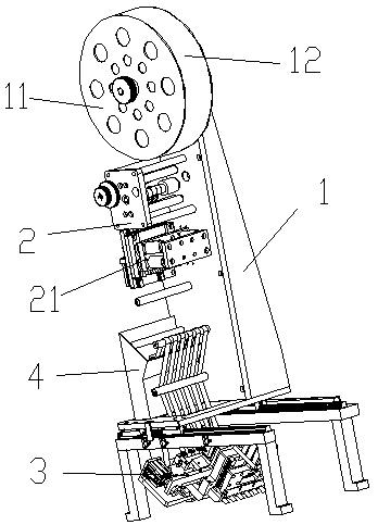
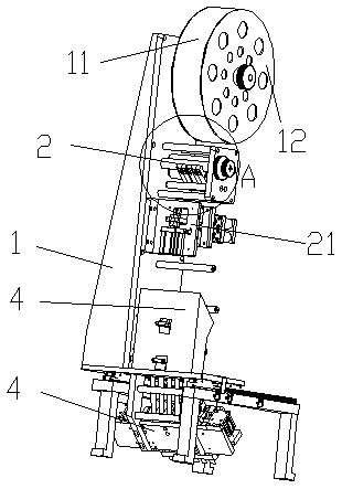
[0037] Such as figure 1 and figure 2 As shown, an automatic placement device for the protective sheet before the battery cover includes a frame 1, and other components are all arranged on the frame 1 in order from top to bottom. The uppermost end of the frame 1 is provided with a rotatable reel 11 on which a purchased roll-shaped protective sheet 12 is placed. Pulled by the lower structure, the reel 11 rotates to release the protective sheet 12 . In this embodiment, in order to clearly show the structure of the automatic placement device, some parts of the protective sheet 12 are not shown in the figure.

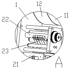
[0038] Such as image 3 and Figure 4 As shown, the strip cutting mechanism 2 is below the reel 11, and the strip cutting mechanism 2 includes a pressing roller 22 and a strip cutting seat 23 arranged on the frame 2. In the present embodiment, the pressing roller 22 is arranged above the strip cutting seat 23, The protective sheet 12 that stretches out from the reel 11 pa...

Embodiment 2

[0047] The structure and method of this embodiment are basically the same as in Embodiment 1, the difference is that the placement hole of the protective sheet 12 is the hole surrounded by the tabs of the battery box, and the battery box needs to be turned over during the capping process, so the protective sheet 12 must be Fasten between the tabs to prevent the battery box from falling out of the hole after being flipped over. At this time, an ejection assembly needs to be set at the edge of the movable plate 36, such as Figure 11 As shown, a plurality of ejector rods 61 are arranged below the ejector assembly, and a power unit 662 is arranged above. In this embodiment, the power part six 62 is a cylinder, and the size of the protective sheet 12 is slightly larger than the size of the hole between the tabs. After the slicer 361 cuts the protective sheet 12, the protective sheet 12 falls on the tab. The power part six 62 Push the ejector assembly 6 to move downward, and the e...

Embodiment 3

[0050] In this example, if Figure 8 As shown, there is an intermediate plate 5 at the outlet of the channel, such as Figure 9 and Figure 10 As shown, the middle plate 5 is provided with a through hole 51, the movable plate 36 is arranged on the top of the middle plate 5, and the slicing knife 361 is positioned at the edge of the through hole 51 near the channel, and the middle plate 5 provides the counteraction of the slicing knife 361 cutting the protective sheet 12. force. An ejector assembly 6 is also arranged above the middle plate 5 , and its ejector rod 61 is matched with the through hole 51 one by one. The placement hole in this embodiment can be the hole in the middle cover or the hole surrounded by the tabs in the battery box. The middle cover or the battery box is transported to the bottom of the middle plate by the transport mechanism. The through holes 51 match the placement holes one by one. The through hole 51 is slightly larger than the placement hole, so ...


PUM


Abstract

The invention discloses an automatic placing method and an automatic placing device for a protective sheet before storage battery capping. The device comprises a rack, which is provided with a strip cutting mechanism connected with a complete protective sheet and used for cutting the protective sheet into strips, and a sheet cutting mechanism connected with the strip-shaped protective sheet and used for cutting the protective sheet into sheets with required lengths, wherein the sheet cutting mechanism is provided with a supporting plate, the supporting plate is provided with a channel for allowing the sheet-shaped protective sheets to pass through, the opening of the channel inclines towards the side lower portion, and a sheet cutting knife is arranged above the edge of the channel; or a middle plate is arranged at the opening of the channel, a through hole is formed in the middle plate from top to bottom, the protective sheet extends to the position above the through hole, and a sheetcutting knife is arranged above the position, close to the side surface of the channel, of the through hole. According to the invention, a protective sheet is divided into a plurality of strips fromone end of the protective sheet through the automatic placing device, the strips are pulled to to-be-placed holes, and the protective sheets meeting the length requirement are spit out through the automatic placing device and cut off, so that the protective sheets can accurately, rapidly and efficiently fall into the placing holes from top to bottom.

Description

technical field [0001] The invention relates to equipment used in the production process of a storage battery, in particular to a method and device for automatically placing a protective sheet before the storage battery is sealed. Background technique [0002] In the production process of the battery, it is necessary to add electrolyte to the battery box after sealing the cover, and to pump the electrolyte after charging and forming, and in the process of adding and pumping the electrolyte, it is necessary to use a protective sheet to wrap the separator of the pole piece Cover it with paper to prevent the pipe hole used for adding or suction from directly touching the separator paper and damage the separator paper and cause a short circuit of the battery. [0003] Most of the protective sheets currently used are plastics with holes, which have a certain hardness, so that they can be processed into the required shape and placed between the battery case and the middle cover, a...

Claims


Application Information

Patent Timeline
Patent Type & Authority Applications(China)
IPC IPC(8): H01M10/04H01M10/12
CPCH01M10/0404H01M10/12Y02E60/10Y02P70/50
Inventor 郑圣泉黎派龙邱达军
Owner ZHUZHOU YINGDING AUTOMATION EQUIP TECH
Why Eureka
Try Eureka