Heat exchange unit and refrigeration cycle device

A heat exchange unit, refrigeration cycle technology, applied in refrigerators, refrigeration components, refrigeration and liquefaction, etc., can solve the problems of difficult manufacturing, complex branch pipe structure, etc., and achieve the effect of simple path balance

Active Publication Date: 2020-04-17
MITSUBISHI ELECTRIC CORP
View PDF6 Cites 4 Cited by
  • Summary
  • Abstract
  • Description
  • Claims
  • Application Information

AI Technical Summary

Problems solved by technology

That is, there is a problem that the structure of the branch pipe in Patent Document 1 is complicated and difficult to manufacture.

Method used


Image

  • Heat exchange unit and refrigeration cycle device
  • Heat exchange unit and refrigeration cycle device
  • Heat exchange unit and refrigeration cycle device

Examples


Embodiment approach 1

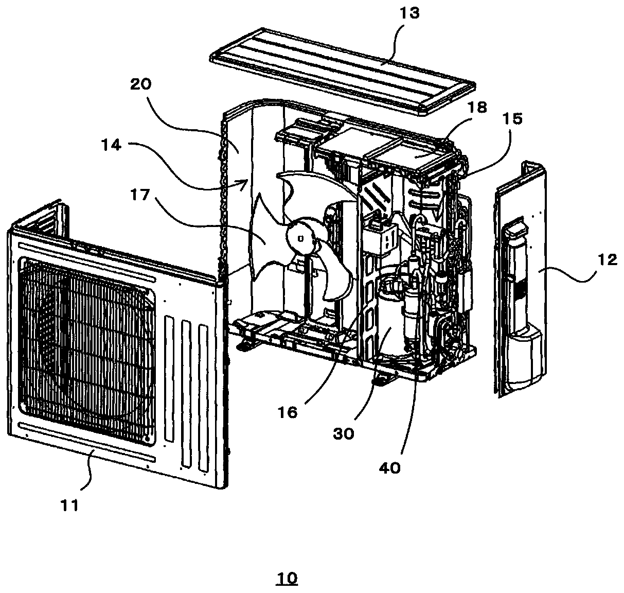
[0027] figure 1 It is an exploded perspective view of the heat exchange unit according to Embodiment 1 of the present invention. Such as figure 1 As shown, in Embodiment 1, the heat exchange unit is the outdoor unit 10 . The casing of the outdoor unit 10 is composed of a front panel 11 , side panels 12 and a top panel 13 . A blower chamber 14 and a machine chamber 15 are formed inside the outdoor unit 10 . The blower chamber 14 and the machine chamber 15 are partitioned by a partition plate 16 .

[0028] The blower chamber 14 is provided with a heat exchanger 20 and a blower 17 for supplying outdoor air to the heat exchanger 20 . A compressor 30 and a refrigerant pipe 40 constituting a part of a refrigeration cycle device described later are provided in a lower portion of the machine compartment 15 . Electrical components 18 are provided on the upper portion of the machine room 15 .

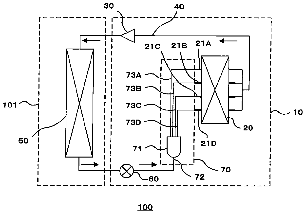
[0029] figure 2 It is a refrigerant circuit diagram of the refrigeration cycle appara...

Embodiment approach 2

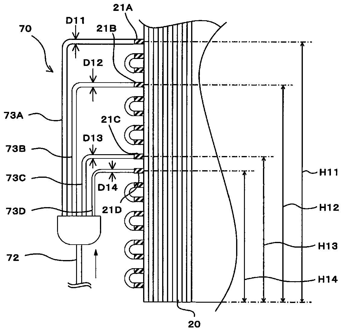
[0035] Figure 4 It is a refrigerant circuit diagram of the refrigeration cycle apparatus in Embodiment 2 of this invention. Figure 5 It is a figure which shows the main part of the heat exchanger concerning Embodiment 2 of this invention. and figure 2 same, Figure 4 is a refrigerant circuit diagram in heating operation, and the flow of refrigerant is indicated by arrows. exist Figure 4 and Figure 5 Herein, the same reference numerals are attached to the same constituent elements as those of the refrigeration cycle apparatus according to Embodiment 1 described above. In refrigeration cycle apparatus 200 according to Embodiment 2, inflow pipe 72 of refrigerant distributor 70 is connected to heat transfer pipe 21E of heat exchanger 20 . That is, the refrigerant distributor 70 is provided inside the heat exchanger 20 which is an evaporator. The other structures are the same as in Embodiment 1, and the inner diameter of the relatively low branch pipe 73 connected to th...

Embodiment approach 3

[0040] Figure 7 It is a refrigerant circuit diagram of the refrigeration cycle apparatus in Embodiment 3 of this invention. Figure 8 It is a figure which shows the main part of the heat exchanger concerning Embodiment 3 of this invention. and figure 2 and Figure 4 same, Figure 7 is a refrigerant circuit diagram in heating operation, and the flow of refrigerant is indicated by arrows. exist Figure 7 and Figure 8 Herein, the same reference signs are assigned to the same constituent elements as those of the refrigeration cycle apparatuses of Embodiment 1 and Embodiment 2 described above. In Embodiment 3, refrigerant distributor 370 and refrigerant distributor 380 are provided in refrigeration cycle apparatus 300 . The refrigerant distributor 370 has a distributor main body 371 , an inflow pipe 372 through which the refrigerant enclosed in the refrigerant pipe 40 flows in, and two branch pipes 373A and 373B through which the refrigerant flows out. The inflow pipe 37...


PUM


Abstract

This heat exchange unit comprises: a heat exchanger having a plurality of heat transfer tubes; and a plurality of refrigerant distributors. Each of the plurality of refrigerant distributors comprisesan inflow tube into which refrigerant flows, and a plurality of flow dividing tubes out of which refrigerant flows. The plurality of flow dividing tubes are connected respectively to the plurality ofheat transfer tubes. The inner diameter of the inflow tubes of a refrigerant distributor having a comparatively lower average value for the height of the connection positions between the plurality offlow dividing tubes and the plurality of heat transfer tubes is smaller than the inner diameter of the inflow tubes of a refrigerant distributor having a comparatively higher average value for the height of the connection positions between the plurality of flow dividing tubes and the plurality of heat transfer tubes. In each of the plurality of refrigerant distributors, the inner diameter of a flow dividing tube from among the plurality of flow dividing tubes which has a comparatively lower connection position with a heat transfer tube is smaller than the inner diameter of a flow dividing tubefrom among the plurality of flow dividing tubes which has a comparatively higher connection position with a heat transfer tube.

Description

technical field [0001] The present invention relates to a refrigeration cycle device used for air conditioning, refrigeration and refrigeration, and a heat exchange unit provided in the refrigeration cycle device. Background technique [0002] Conventionally, a refrigerant distributor is provided in order to increase the heat exchange efficiency of a heat exchanger provided in a heat exchange unit of a refrigeration cycle apparatus. The refrigerant distributor includes: an inflow pipe connected to an opening end through which the refrigerant flows in; and a plurality of branch pipes respectively connected to a plurality of opening ends through which the refrigerant flows out. In such a refrigerant distributor, in order to increase the heat exchange rate in the heat exchanger, it is required to make the outflow of the fluid uniform and to balance the path after the flow is divided appropriately. For example, Patent Document 1 describes a configuration in which a cylindrical ...

Claims


Application Information

Patent Timeline
Patent Type & Authority Applications(China)
IPC IPC(8): F25B41/00F25B39/02
CPCF25B39/028F25B39/04F25B41/00F25B41/42F25B39/00
Inventor 荒木良平
Owner MITSUBISHI ELECTRIC CORP
Why Eureka
Try Eureka