
Method and device for reducing speed of cutter

A cutting knife and speed technology, applied in printing devices, printing, metal processing, etc., can solve problems such as cutter damage, bumping into the printer, and poor printer body

Inactive Publication Date: 2020-04-21
湖南鼎一致远科技发展股份有限公司
View PDF7 Cites 0 Cited by
  • Summary
  • Abstract
  • Description
  • Claims
  • Application Information

AI Technical Summary

Problems solved by technology

[0002] In the paper cutting module of the printer, the cutter is easy to hit the side wall of the printer at a high speed after cutting the paper, which will cause damage to the cutter and is not good for the main body of the printer

Method used


Image

  • Method and device for reducing speed of cutter
  • Method and device for reducing speed of cutter
  • Method and device for reducing speed of cutter

Examples


Embodiment Construction

[0028] The principles and features of the present invention are described below, and the examples given are only used to explain the present invention, and are not intended to limit the scope of the present invention.

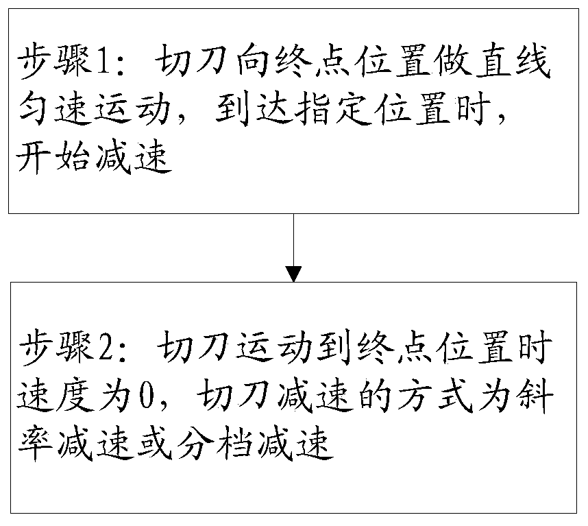
[0029] like Figure 1-Figure 3 As shown, the present embodiment relates to a cutting knife deceleration method, comprising the following steps:

[0030] Step 1: The cutter moves toward the end position in a straight line at a constant speed, and when it reaches the designated position, it starts to decelerate;

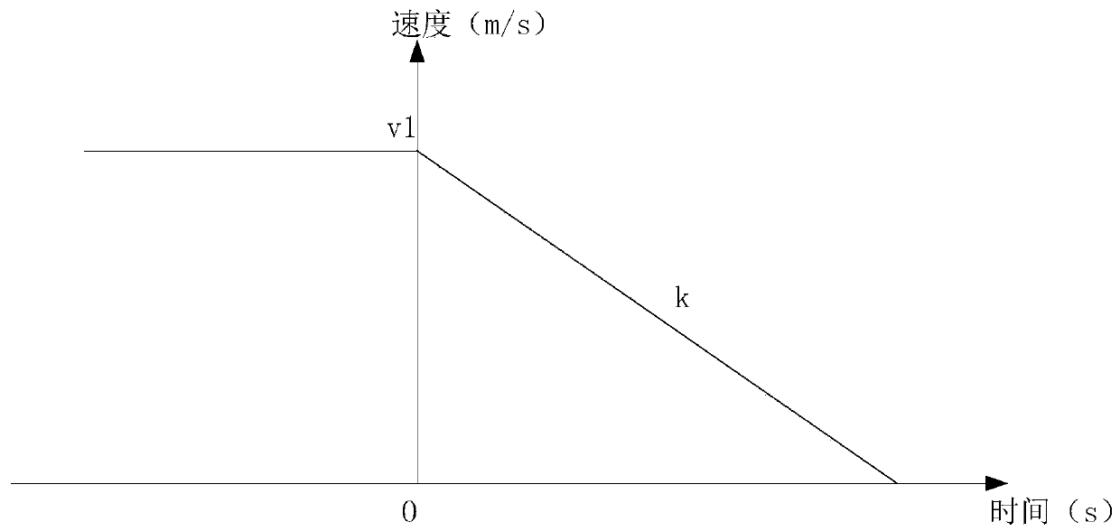
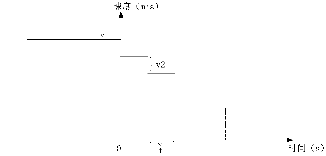
[0031] Step 2: When the cutter moves to the end position, the speed is 0.

[0032] As a further solution of this embodiment, in the step 1, the time for the cutter to move at a constant speed is set so that the cutter reaches a designated position and starts to decelerate.

[0033] As a further solution of this embodiment, in the step 1, a deceleration detection sensor is installed at a designated position, and the cutter moves at a constant speed unt...


PUM


Abstract

The invention relates to a method and device for reducing the speed of a cutter. The method comprises the steps that 1, the cutter makes linear and uniform motion to a final position and starts reducing the speed when reaching a specified position; and 2, the speed is 0 when the cutter moves to the final position. The speed reduction mode of the cutter is slope speed reduction or graded speed reduction. The method has the beneficial effects that the specific time is set in the system in the sliding process of the cutter, and the cutter stops after moving for the specific time.

Description

technical field [0001] The invention relates to the field of printers, in particular to a cutting knife deceleration method and device. Background technique [0002] In the paper cutting module of the printer, the cutter is easy to hit the side wall of the printer at a high speed after cutting the paper, which will cause damage to the cutter and is not good for the main body of the printer. [0003] Therefore, those skilled in the art urgently need a cutter deceleration method and device. Contents of the invention [0004] The technical problem to be solved by the invention is to prevent the cutter from colliding with the side wall of the printer at high speed after cutting paper. [0005] The technical solution of the present invention to solve the above-mentioned technical problem is as follows: a kind of cutter deceleration method, comprises the following steps: [0006] Step 1: The cutter moves toward the end position in a straight line at a constant speed, and when ...

Claims


Application Information

Patent Timeline
Patent Type & Authority Applications(China)
IPC IPC(8): B26D5/00B26D7/22B41J11/70
CPCB26D5/005B26D7/22B26D2005/002B41J11/70
Inventor 李留祥唐国初
Owner 湖南鼎一致远科技发展股份有限公司
Learn More