Full-plastic foam pump

A foam pump and seat body technology, applied in the field of foam pumps, can solve problems such as poor liquid atomization performance

Pending Publication Date: 2020-04-21
ZHONGSHAN LEUNCHEONG DISPENSING PUMP
View PDF0 Cites 8 Cited by
  • Summary
  • Abstract
  • Description
  • Claims
  • Application Information

AI Technical Summary

Problems solved by technology

The problem is: after the air flow enters the diversion sleeve, a vortex is generated, and the atomization performance of the liquid is poor

Method used


Image

  • Full-plastic foam pump
  • Full-plastic foam pump
  • Full-plastic foam pump

Examples


Embodiment Construction

[0021] The present invention will be further described below in conjunction with the accompanying drawings.

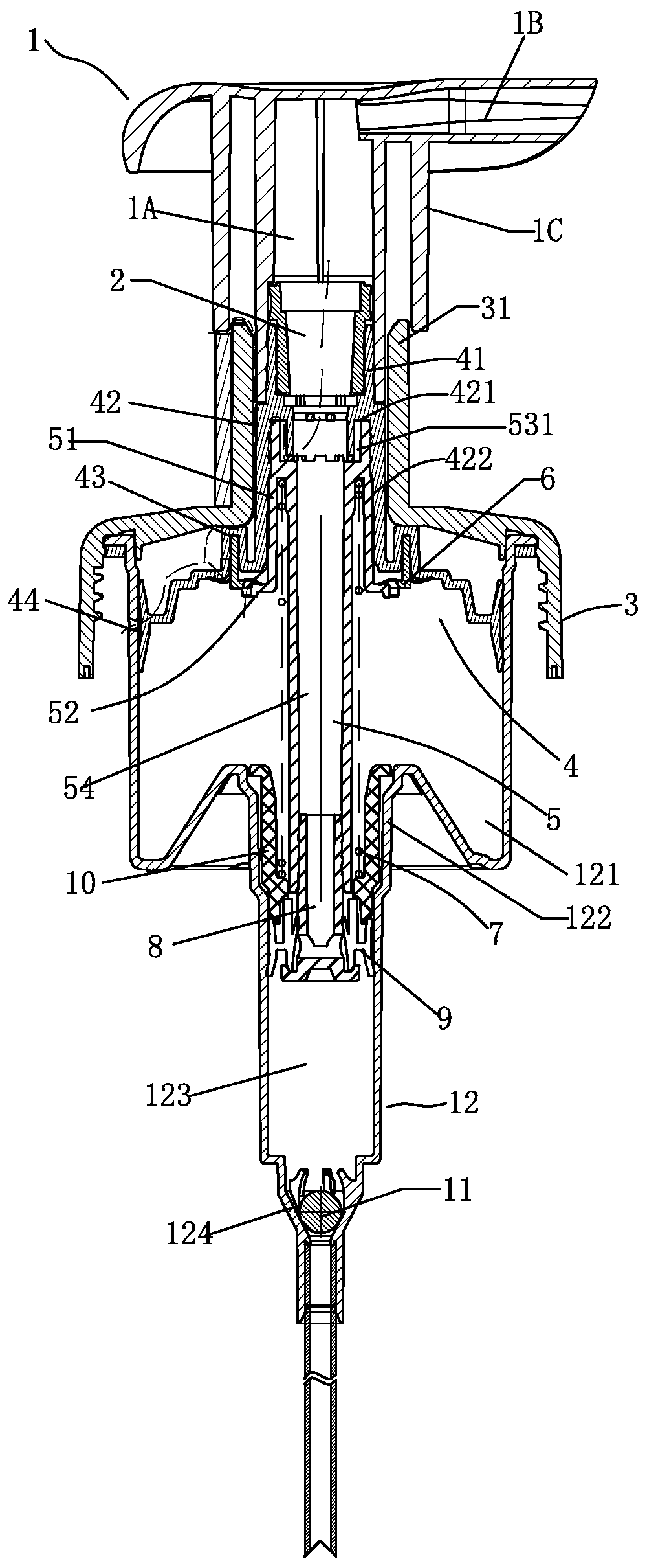
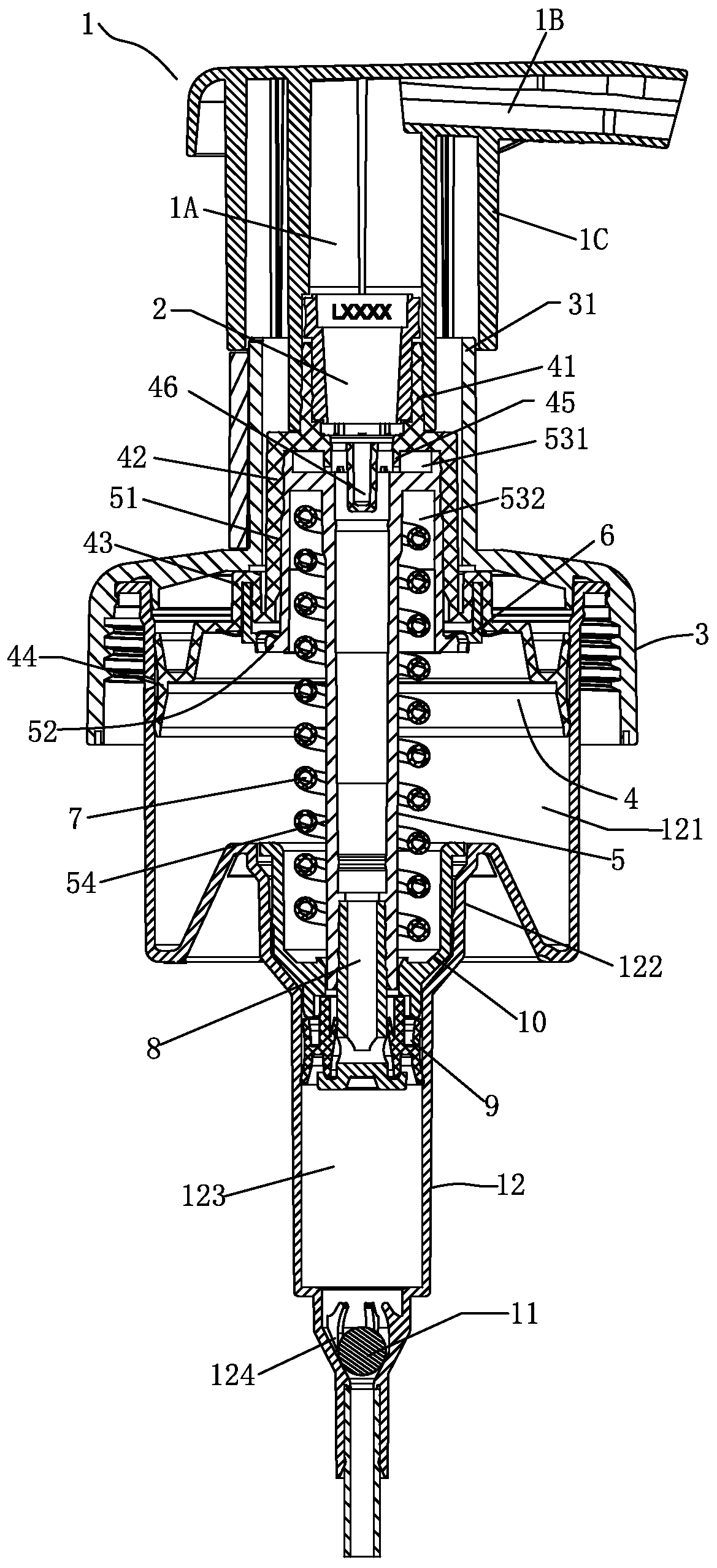
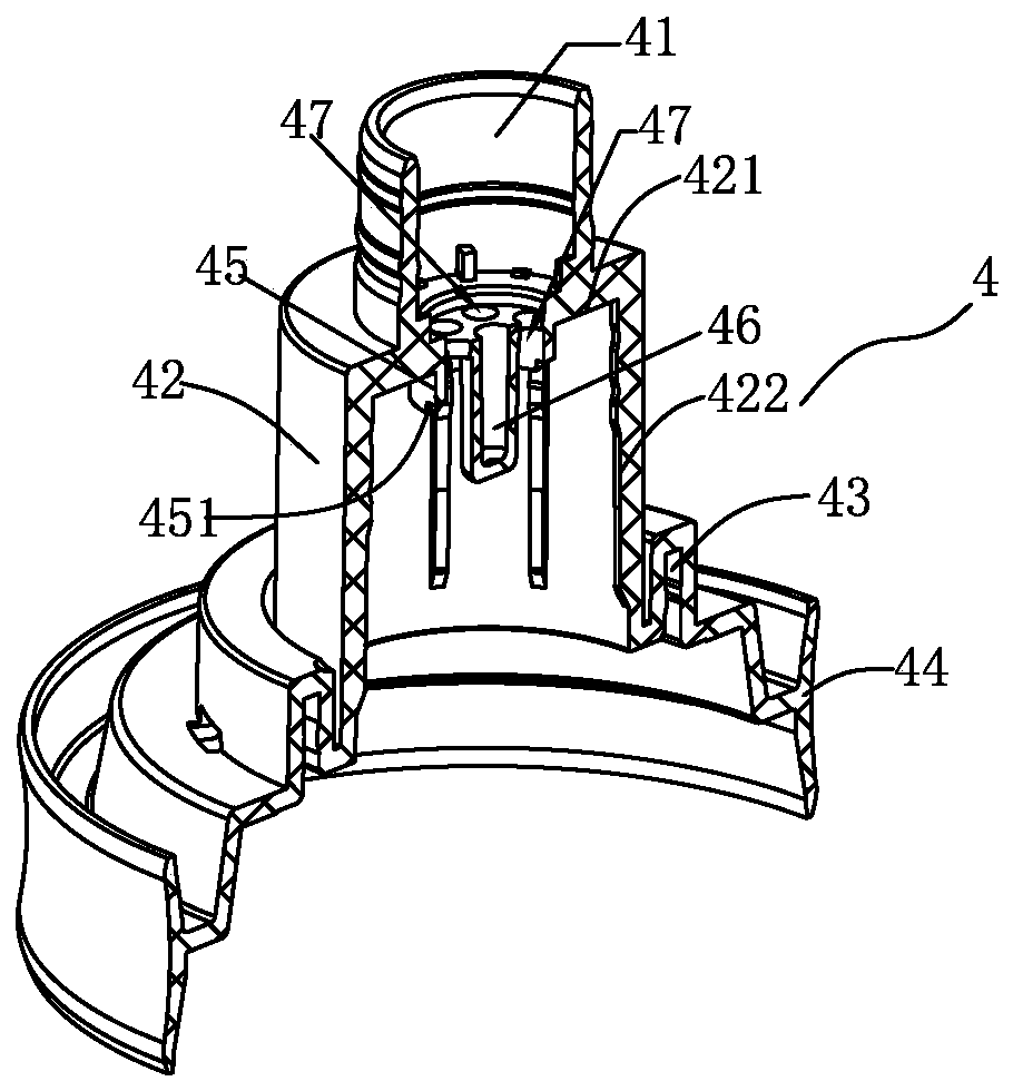
[0022] Such as figure 2 As shown, an all-plastic foam pump includes a press head 1, a net 2, a thread 3, a large piston 4, a connecting rod 5, a valve 6, an elastic body 7, an auxiliary column 8, a small piston 9, a piston seat 10, a ball 11 and the body 12, the head 1 includes the liquid inlet channel 1A, the liquid outlet channel 1B and the sleeve 1C, the thread 3 is provided with a guide sleeve 31; the large piston 4 includes an upper interface 41, a hollow lower opening seat 42, and a valve The fixed seat 43 and the piston main body 44, the top plate of the seat body 42 is provided with a radial rib 421, the inner peripheral wall is provided with an axial rib 422, the radial rib 421 and the axial rib 422 are connected, and the axial rib 422 is provided with a protrusion, and the seat body top plate at the intersection of the upper interface 41 and the seat body 4...


PUM


Abstract

The invention discloses a full-plastic foam pump. The pump comprises a press head, a net connection, a thread, a large piston, a connecting rod, a valve, an elastomer, a secondary column, a small piston, a piston seat, a ball and a body, a gas-liquid flow guiding device comprises a gas-liquid mixing cavity arranged on a top plate of a seat body, a flow guiding column located in the gas-liquid mixing cavity and connected with the top plate, and a plurality of gas-liquid mixing holes arranged around the flow guiding column and in the top plate, wherein a gas flow guiding groove is formed in thelower end of the gas-liquid mixing cavity; the flow guiding column extends into a connecting pipe, a gap is formed between the flow guiding column and the connecting pipe, and the lower end of the gas-liquid mixing cavity is attached to a partition plate between an upper cavity and a lower cavity. Due to adoption of the structure, airflow surrounds a liquid flow, then pressurizing and diffusing are conducted, no vortex is generated, the atomization performance is improved, and the flow speed is accelerated.

Description

technical field [0001] The invention relates to a foam pump. Background technique [0002] Existing technologies such as figure 1 As shown, a foam pump includes a press head 1, a net 2, a screw 3, a large piston 4, a connecting rod 5, a valve 6, an elastic body 7, an auxiliary column 8, a small piston 9, a piston seat 10, a ball 11 and The body 12, the press head 1 includes the liquid inlet channel 1A, the liquid outlet channel 1B and the sleeve 1C, the thread 3 is provided with a guide sleeve 31; the large piston 4 includes an upper interface 41, a hollow lower opening seat 42, and a valve fixing seat 43 and the piston main body 44, the top plate of the seat body 42 is provided with a radial rib 421, the inner peripheral wall is provided with an axial rib 422, the radial rib 421 and the axial rib 422 are connected, and the axial rib 422 Protrusions are provided, and a gas-liquid flow guiding device is provided on the seat top plate at the intersection of the upper interfa...

Claims


Application Information

Patent Timeline
IPC IPC(8): B65D47/34
CPCB05B11/1001B05B11/1042B05B11/1023B05B11/1047B05B11/1077B05B11/1087
Inventor 林添大张金明莫恒进
Owner ZHONGSHAN LEUNCHEONG DISPENSING PUMP
Why Eureka
Try Eureka