centrifugal spinning frame
A spinning frame and centrifugal technology, applied in spinning machines, continuous winding spinning machines, textiles and papermaking, etc., can solve problems such as yarn cake damage, high winding failure, and difficulty in removing the inner cover, etc. To achieve the effect of increasing the success rate
- Summary
- Abstract
- Description
- Claims
- Application Information
AI Technical Summary
Problems solved by technology
Method used
Image

Examples
no. 1 approach
[0041]
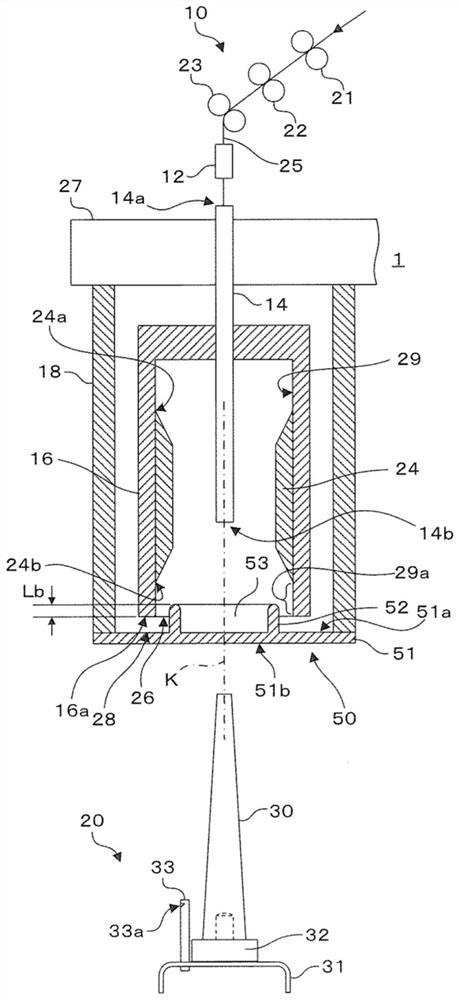
[0042] figure 1 It is a schematic diagram showing the structure of the centrifugal spinning frame according to the first embodiment of the present invention.
[0043] Such as figure 1 As shown, the centrifugal spinning frame 1 includes a drafting device 10 , a hair suction tube 12 , a yarn guide tube 14 , a centrifugal tank 16 , a fixed cover 18 , a bobbin support portion 20 and a cover 50 . In addition, the above-mentioned constituent elements constitute one spindle as one unit of spinning. The centrifugal spinning frame 1 includes a plurality of spindles, and the structure of one of the spindles will be described here.
[0044] (drafting device)
[0045] The drafting device 10 is a device for drawing a yarn material. The draft device 10 is configured using a plurality of roller pairs including a rear roller pair 21 , an intermediate roller pair 22 , and a front roller pair 23 . The plurality of roller pairs are arranged in the order of the rear roller pair 21...
no. 1 approach effect
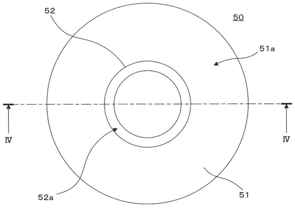
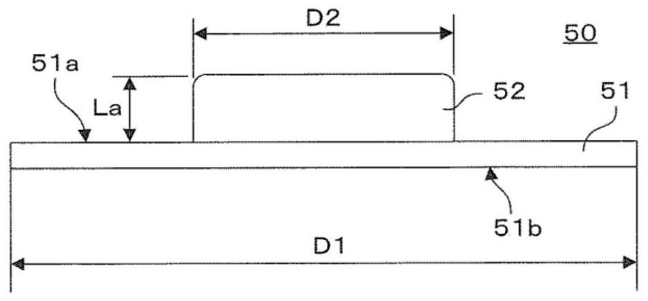
[0128] In the first embodiment of the present invention, the following structure is adopted, that is, the cover 50 that closes the cover opening 28 of the fixed cover 18 is provided, and when the cover opening 28 is closed with the cover 50, the centrifuge tank 16 is used to The protruding portion 52 arranged inward is configured to guide the yarn toward the inner wall 29 of the centrifuge tank 16 . Accordingly, the yarn serving as the winding starting point can be reliably wound around the inner wall region 29 a of the centrifugal pot 16 . Therefore, the success rate of rewinding to the bobbin 30 can be improved without technical difficulties such as removing the inner cover from the rotating centrifuge can.
[0129] In addition, in the first embodiment of the present invention, when the cover opening 28 of the fixed cover 18 is closed by the cover 50, the entry amount Lb of the protruding part 52 based on the lower end part 16a of the centrifuge tank 16 is ensured as 0.1mm ...
no. 2 approach
[0132] However, in the case of yarn breakage as described above, a part of the yarn protruding from the yarn discharge port 14b of the yarn guide tube 14 is separated from the inner wall 29 of the centrifuge tank 16 and exists in the space in the centrifuge tank 16 as it is. Condition. Thus, the yarns that exist away from the inner wall 29 of the centrifuge pot 16 are called "chords". In this specification, the yarn forming the string is referred to as "string yarn". The string yarn is bent by the centrifugal force accompanying the rotation of the centrifuge pot 16 , and exists independently from the yarn wound around the inner wall 29 of the centrifuge pot 16 .
[0133] As described above, if the string yarn exists in the space in the centrifuge tank 16 , the string yarn may come into contact with the outer peripheral surface of the yarn guide tube 14 , so that the string yarn may be wound around the yarn guide tube 14 . In addition, for example, when the bobbin 30 is inser...
PUM
 Abstract
Description
Claims
Application Information
 - R&D
- Intellectual Property
- Life Sciences
- Materials
- Tech Scout
- Unparalleled Data Quality
- Higher Quality Content
- 60% Fewer Hallucinations
Browse by: Latest US Patents, China's latest patents, Technical Efficacy Thesaurus, Application Domain, Technology Topic, Popular Technical Reports.
© 2025 PatSnap. All rights reserved.Legal|Privacy policy|Modern Slavery Act Transparency Statement|Sitemap|About US| Contact US: help@patsnap.com