
Roadbed maintenance device and method for road construction

A technology of roadbed and highway, applied in the direction of roads, roads, road repair, etc., can solve the problems of poor spraying method, low work efficiency, inconvenient operation, etc., and achieve the effect of simple and convenient control, high work efficiency, and reduction of collisions.

Active Publication Date: 2022-02-11
兰陵县交通运输局
View PDF7 Cites 0 Cited by
  • Summary
  • Abstract
  • Description
  • Claims
  • Application Information

AI Technical Summary

Problems solved by technology

[0003] And the wetting maintenance of prior art is generally by artificially laying felt on the surface of the roadbed, and then artificially sprinkles water on the surface of the felt to moisten, and such mode makes work efficiency low, laborious; A municipal highway construction and maintenance cleaning vehicle, which includes a car body, a vacuum water pump 101, an infrared deicer 200 and a sprinkler 106. The top of the car body 100 is located on the side of the vacuum water pump 101 and is fixed with a water tank 102 by bolts. The water tank 102 can be used to hold Keeping and protecting water, the top of the car body 100 is located on the side of the water tank 102 and is fixed with a rotating seat 103 by bolts. The center of the rotating seat 103 is installed with a felt cloth roll 104 through the rotation of the rotating shaft, which can be used to hold the felt cloth roll 104. To make the covering work easier, the center of the bottom of the car body 100 is fixed with a rotating brush plate 108 by bolts, which can sweep the garbage on the road into the adsorption range of the dust suction port 107. A suction port 107 is movable on one side of the brush plate 108 to suck the garbage into the car body 100 for storage. The bottom of the car body 100 is far away from the infrared deicer 200 and the end is fixed with a water pipe 105 through a clamp. The two ends of the water pipe 105 The sprinkler 106 is welded, and after the maintenance water in the water tank is pressurized by the water pump, the spray is sprayed onto the road surface, but this spraying method is not convenient, and the operation is inconvenient. machinery to lay felt and spray water at the same time, so that roadbed maintenance can be carried out quickly, but currently there is no effective equipment to realize this technical means

Method used


Image

  • Roadbed maintenance device and method for road construction
  • Roadbed maintenance device and method for road construction
  • Roadbed maintenance device and method for road construction

Examples


Embodiment 1

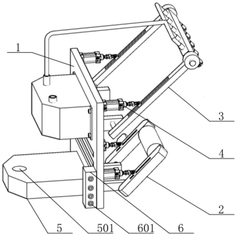
[0038] see figure 1 —8. Roadbed maintenance device for road construction, including installation board 1, laying mechanism 2, spraying mechanism 3, and push-pull mechanism 4;

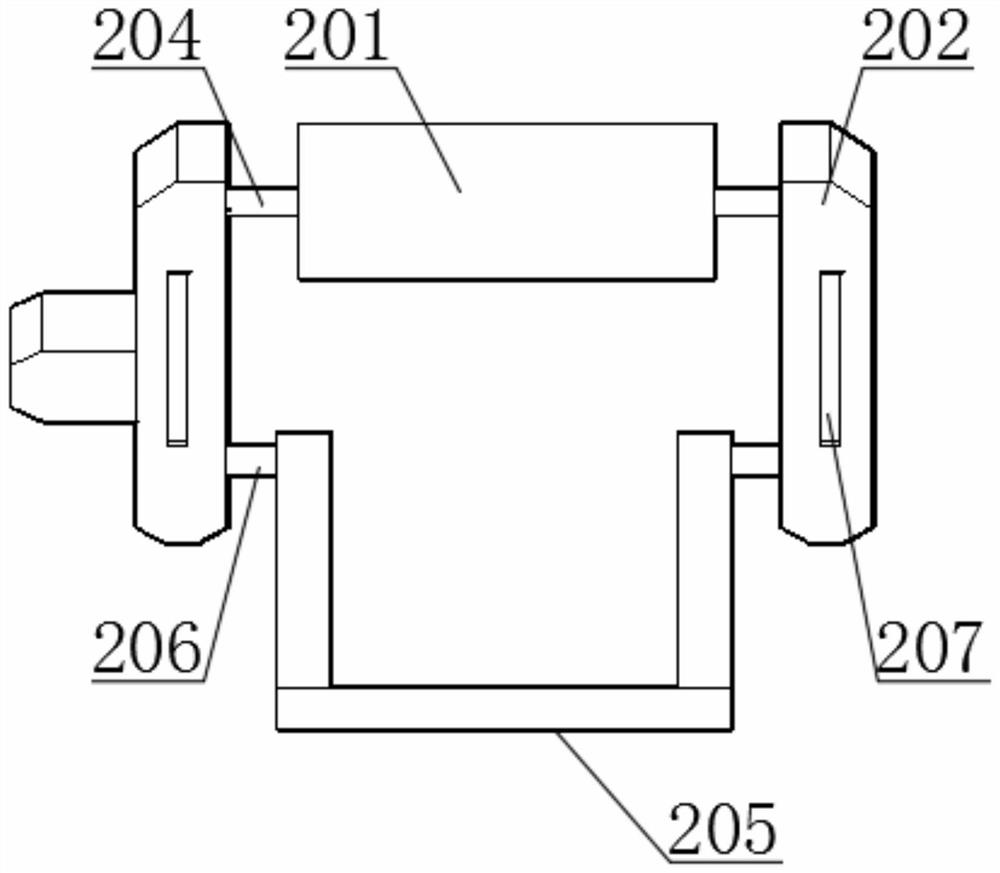
[0039]The laying mechanism 2 includes a drum 201, a side frame 202, and a rotating motor 203. Felt is rolled on the upper part of the drum 201. Both ends of the drum 201 are fixedly connected to a No. 1 rotating shaft 204. Two groups of No. 1 rotating shafts 204 are respectively connected to a group of side frames through bearings. In 202, a rotating motor 203 is fixedly installed on the side of one group of side frames 202, and a protective shell is arranged on the outside of the rotating motor 203, and the rotating motor 203 is power-connected with the No. The motor 203 can drive the drum 201 to rotate, and the mounting plate 1 is fixedly connected with a No. 1 turret 205. Both sides of the No. 1 turret 205 are fixedly connected with a No. 2 rotating shaft 206, and the No. 2 rotating shaft 206 is resp...

Embodiment 2

[0043] see figure 1 —8. The roadbed maintenance device for road construction is basically the same as the first embodiment. What’s more, the mounting plate 1 is fixedly connected with the hanger 5 at the bottom of the water storage tank 304, and the hanger 5 is provided with a mounting hole 501. Frame 5 is used to fixedly install the maintenance device on the maintenance vehicle;

[0044] Further on the mounting plate 1, one side of the hanger 5 is fixedly installed with a control mechanism 6. The control mechanism 6 includes a control shell and a controller with a single-chip microcomputer installed inside the control shell. The controller is connected to the rotating motor 203, The water pump and each group of hydraulic telescopic cylinders are connected to signal 401 to control their work;

[0045] Multiple sets of data connectors 601 are installed on the control shell, and the data connectors 601 are connected to the controller signal. There is a control panel in the cab ...

Embodiment 3

[0048] see figure 1 —8. Roadbed maintenance device for road construction. In Embodiment 1, the power connection between the rotating motor 203 and the No. 1 rotating shaft 204 adopts the following structure. The rotating shaft of the rotating motor 203 is fixedly connected with a No. 1 gear 7, and a gear 7 on the same side as it is The No. 2 gear 8 is fixedly connected to the No. 2 rotating shaft 204 , and the No. 1 gear 7 and the No. 2 gear 8 are connected through a chain 9 .

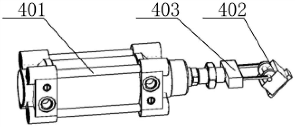
[0049] In the first embodiment, the sliding block 402 includes a bottom sliding block 40201, an upper sliding block 40202, and a rotating block 40203. The upper part of the bottom sliding block 40201 is fixedly connected with the upper sliding block 40202, and the symmetrical fixed connection of the upper sliding block 40202 has two sets of rotating blocks. block 40203, and is slidably connected in the No. 1 chute 207 or No. 2 chute 309 by the bottom slider 40201, and the connecting piece 403 includes ...


PUM


Abstract

The invention discloses a roadbed maintenance device for road construction, which comprises a mounting plate, a laying mechanism, a spraying mechanism, and a push-pull mechanism. Through the laying mechanism, felt can be laid on the surface of the roadbed from a roller. Wet, so as to achieve the wet maintenance of the roadbed. The invention has the advantages of accelerating maintenance efficiency, enhancing service life, and simple and convenient operation and control.

Description

technical field [0001] The invention relates to the technical field of road construction, in particular to a road bed maintenance device and method for road construction. Background technique [0002] For the concrete roadbed in the expressway, after the construction is completed, in order to ensure the good solidification of the concrete, it is necessary to ensure that the concrete is in a relatively humid environment. It is mainly to maintain the hydration conditions of the concrete. [0003] And the wetting maintenance of prior art is generally by artificially laying felt on the surface of the roadbed, and then artificially sprinkles water on the surface of the felt to moisten, and such mode makes work efficiency low, laborious; A municipal highway construction and maintenance cleaning vehicle, which includes a car body, a vacuum water pump 101, an infrared deicer 200 and a sprinkler 106. The top of the car body 100 is located on the side of the vacuum water pump 101 and...

Claims


Application Information

Patent Timeline
Patent Type & Authority Patents(China)
IPC IPC(8): E01C23/03E01C3/00E01C3/02C04B40/02
CPCE01C23/03E01C3/00E01C3/02C04B40/0277
Inventor 李晓梁日全
Owner 兰陵县交通运输局
Learn More