Assembling device for magnetic damping shock absorbers

A technology for assembling devices and shock absorbers, which is applied in spring/shock absorber manufacturing, spring/shock absorbers, magnetic springs, etc., can solve problems such as interference with magnet installation, large manpower and time, and instability of permanent magnets, etc., to achieve Solve assembly problems, install safely and accurately, and improve assembly accuracy

Active Publication Date: 2020-04-21
ZHONGBEI UNIV
View PDF6 Cites 4 Cited by
  • Summary
  • Abstract
  • Description
  • Claims
  • Application Information

AI Technical Summary

Problems solved by technology

[0002] The set of permanent magnets in the magnetic damping shock absorber is usually manually operated. The general assembly mode not only consumes a lot of manpower and time, but also due to the existence of strong magnetic force between the magnets, the ultimate compression will bring the ultimate strong magnetic force. Under the action of strong magnetic force, the permanent magnet flies out, which poses a great threat to the personal safety of the installation workers. Due to the interference of strong magnetic force, the permanent magnet has been in an unstable state, and it will also interfere with the installation of the next magnet, which greatly weakens the In order to improve the installation efficiency, after the permanent magnet and the central rod are installed, they need to be assembled with the metal outer cylinder as a whole, but the strong magnetic attraction between the permanent magnet and the metal outer cylinder will interfere with the permanent magnet, the central rod and the metal outer cylinder. center fit accuracy

Method used


Image

  • Assembling device for magnetic damping shock absorbers
  • Assembling device for magnetic damping shock absorbers
  • Assembling device for magnetic damping shock absorbers

Examples


Embodiment Construction

[0016] The technical solution of the present invention will be described in further detail below in conjunction with the accompanying drawings and specific embodiments.

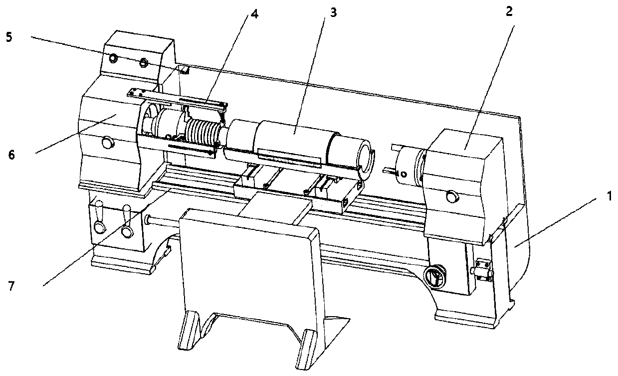
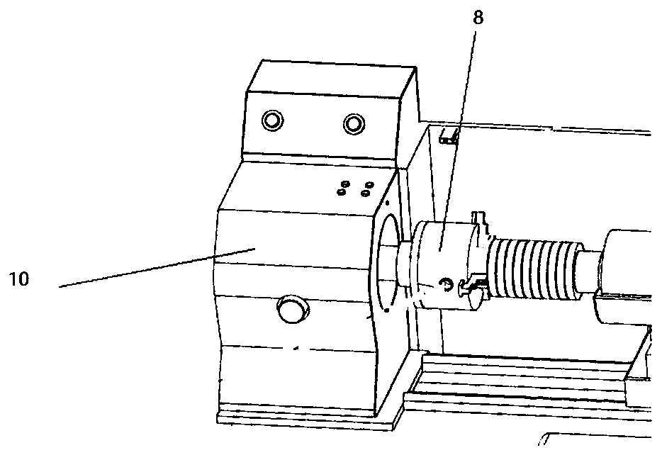
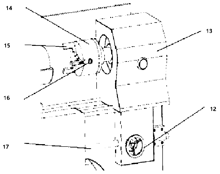
[0017] Such as Figure 1 to Figure 5 As shown, the assembly device of a magnetic damping shock absorber of the present invention includes a platform base 1, a guide rail 7, a central rod clamping device 6, a permanent magnet ring clamping device 2, a metal outer cylinder fixing device 3, and a coaxial detection device 5 and 2 limit devices 4. Two guide rails 7 are fixed and installed on the upper surface of the platform base 1 in parallel. The central rod clamping device 6 and the permanent magnet ring clamping device 2 are slidingly connected to the two ends of the two guide rails 7 respectively, and the central rod clamping device 6 and the permanent magnet ring clamping device 2 can move along the guide rails. Both the lower end of the central rod clamping device 6 and the lower end of the permanent magne...


PUM


Abstract

The invention relates to an assembling device for magnetic damping shock absorbers. The assembling device comprises a platform base (1), two guiderails (7), a center rod clamping device (6), a permanent magnetic iron hoop clamping device (2), a metal outer barrel fixing device and two limiting devices, wherein the two guiderails are fixed mounted on the upper surface of the platform base in parallel; the center rod clamping device and the permanent magnetic iron hoop clamping device are respectively connected with two ends of the two guiderails in a sliding manner; nuts are arranged at both the lower end of the center rod clamping device (6) and the lower end of the permanent magnetic iron hoop clamping device; the two nuts are respectively screwed at two ends of a lead screw guiderail; the metal outer barrel fixing device comprises a support (44), a slide (34) and a metal outer barrel; each limiting device comprises a limiting rod, a spring and a limiting pin (22); and the permanent magnetic iron hoop clamping device and the center rod clamping device are the same in the aspect of structure. The assembling device is capable of solving the assembling difficulties of consuming plenty of labor and time and being low in mounting efficiency in the assembling process of the magnetic damping shock absorbers, and then improving the assembling precision.

Description

technical field [0001] The invention belongs to the technical field of assembly of magnetic damping shock absorbers, and in particular relates to an assembly device of magnetic damping shock absorbers. Background technique [0002] The set of permanent magnets in the magnetic damping shock absorber is usually manually operated. The general assembly mode not only consumes a lot of manpower and time, but also due to the existence of strong magnetic force between the magnets, the ultimate compression will bring the ultimate strong magnetic force. Under the action of strong magnetic force, the permanent magnet flies out, which poses a great threat to the personal safety of the installation workers. Due to the interference of strong magnetic force, the permanent magnet has been in an unstable state, and it will also interfere with the installation of the next magnet, which greatly weakens the In order to improve the installation efficiency, after the permanent magnet and the cent...

Claims


Application Information

Patent Timeline
Patent Type & Authority Applications(China)
IPC IPC(8): F16F6/00B23P19/04
CPCB23P19/04F16F6/005F16F2226/04
Inventor 韩晓明张超李强赵慧文翟明辉张浩李侃伟吕孟恩
Owner ZHONGBEI UNIV
Why Eureka
Try Eureka