
Linear motor thrust measuring device and measuring method

A technology of linear motors and measuring devices, applied in measuring devices, motor generator testing, force/torque/power measuring instruments, etc., can solve the problems of easy fatigue, reduce service life, increase costs, etc., and achieve simple structure of measuring devices, The effect of maintaining detection accuracy and protecting loss

Inactive Publication Date: 2020-04-21
NINGBO INST OF MATERIALS TECH & ENG CHINESE ACADEMY OF SCI
View PDF8 Cites 4 Cited by
  • Summary
  • Abstract
  • Description
  • Claims
  • Application Information

AI Technical Summary

Problems solved by technology

The problems of this measurement method are: (1) due to the transmission and control of the signal, the force sensor is connected to the input and output lines, and the movement of the force sensor during the test will inevitably require additional towline management, which will increase the cost and increase The complexity of the measuring device; (2) The working principle of the force sensor is generally that the strain material is deformed under the action of force to cause changes in electrical signals, etc. The continuous reciprocating motion of the force sensor will affect the sensitivity of the strain material to deformation, and it is easy to fatigue. Thereby reduce the measurement accuracy of force sensor, also cause force sensor loss simultaneously, reduce its service life; (3) all comprise in the above-mentioned measuring device and be used for applying the load of braking force to linear motor to be measured, be referred to as braking force load in the present invention, For example, CN203116897U is a heavy object connected with a traction rope that goes around the pulley, CN107314851A is a load linear motor composed of a rotary servo motor, a ball screw and a nut, and CN110160696A is an accompanying linear motor. The sensor is connected to the mover of the linear motor to be tested, which is different from placing the actual load on the linear motor in the actual application of the linear motor. Therefore, the measuring device provided in the above patent document cannot measure the thrust measurement when the load is placed above the linear motor in actual application.

Method used


Image

  • Linear motor thrust measuring device and measuring method

Examples


Embodiment 1

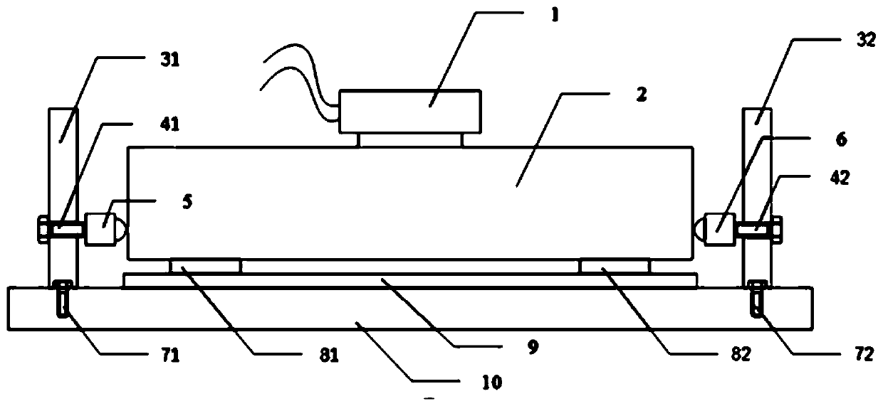
[0039] Such as figure 1 As shown, the linear motor thrust measurement device includes a test platform 10 , a linear motor, a first baffle 31 , a second baffle 32 , a first force sensor 5 , and a second force sensor 6 .

[0040] The linear motor includes a mover 1, a stator 2, a first slider (not shown in the figure) and a first track (not shown in the figure), the mover 1 is fixed on the first slider, and can follow the first slider It moves linearly relative to the stator 2 on the first track.

[0041] The second track 9 is fixed on the test platform 10 . The stator 2 is fixed on the second slider, such as figure 1 As shown, the second sliding piece in this embodiment is composed of the second sliding piece A81 and the second sliding piece B82, and the stator can slide along the second track 9 along with the second sliding piece.

[0042] Along the direction of the second track, the left end of the stator 2 is marked as the stator A end, and the right end is marked as the ...

Embodiment 2

[0052] In this embodiment, the linear motor thrust measuring device is completely the same as that in Embodiment 1.

[0053] In this embodiment, the method of measuring the electromagnetic thrust of the linear motor by using the above-mentioned measuring device is basically the same as that of the embodiment, the difference is that in step (2), the linear motor is energized, the mover has a load, and moves under the action of the electromagnetic thrust. The stator carries the load and moves linearly relative to the stator along the first track.

Embodiment 3

[0055] In this embodiment, the linear motor thrust measuring device is basically the same as that in Embodiment 1. The difference is that the other end of the first force sensor is connected to the end of the stator A through a first rigid connection, and the other end of the second force sensor is connected to the end of the stator B through a second rigid connection.

[0056] The method of measuring the electromagnetic thrust of the linear motor by using the above-mentioned measuring device is the same as that in Embodiment 1.


PUM


Abstract

The invention provides a linear motor thrust measuring device and a linear motor thrust measuring method. The linear motor thrust measuring device comprises a linear motor and a test platform, whereinthe linear motor comprises a stator and a rotor, and the rotor is fixed on a first sliding block and can linearly move on a first rail relative to the stator along with the first sliding block; a second rail is arranged on the test platform, and the stator is fixed on the second sliding block and can slide along the second rail along with the second sliding sheet; baffles are fixedly arranged atthe two ends of the stator respectively, force sensors are arranged between the baffles and the stator end, the stator is clamped between the two force sensors, the two force sensors are used for detecting counter-acting forces, and therefore electromagnetic thrust of the linear motor is obtained. The linear motor thrust measuring device is simple in structure, the force sensors are static in themeasuring process, extra drag chain wire arrangement is not needed, the loss of the force sensors is small, and the measuring device can be used for measuring the electromagnetic thrust of a no-load linear motor and can further be used for measuring the electromagnetic thrust when a rotor is loaded with a load.

Description

technical field [0001] The invention belongs to the technical field of linear motors, and in particular relates to a linear motor thrust measuring device and a measuring method. Background technique [0002] In the field of modern processing industry, high-speed and high-precision linear motion is required in many occasions such as high-speed grinding machines and precision lathes. There are two main methods to obtain linear motion, one is to convert the rotary motion into linear motion by driving the mechanical transmission mechanism through a rotating motor; the other is to directly use a linear motor to drive. The former has disadvantages such as large inertia, high friction, and low repeat positioning accuracy. Therefore, linear motor technology has attracted more and more attention in recent years. [0003] A linear motor is a power device that directly converts electrical energy into mechanical energy for linear motion. The driving performance of the linear motor mai...

Claims


Application Information

Patent Timeline
Patent Type & Authority Applications(China)
IPC IPC(8): G01L5/00G01R31/34
CPCG01L5/0038G01R31/34
Inventor 邱书恒张驰陈飞雪楼昌盛陈进华张杰
Owner NINGBO INST OF MATERIALS TECH & ENG CHINESE ACADEMY OF SCI
Learn More