imaging lens
A technology of imaging lens and lens, applied in the field of imaging lens
- Summary
- Abstract
- Description
- Claims
- Application Information
AI Technical Summary
Problems solved by technology
Method used
Image

Examples
Embodiment Construction
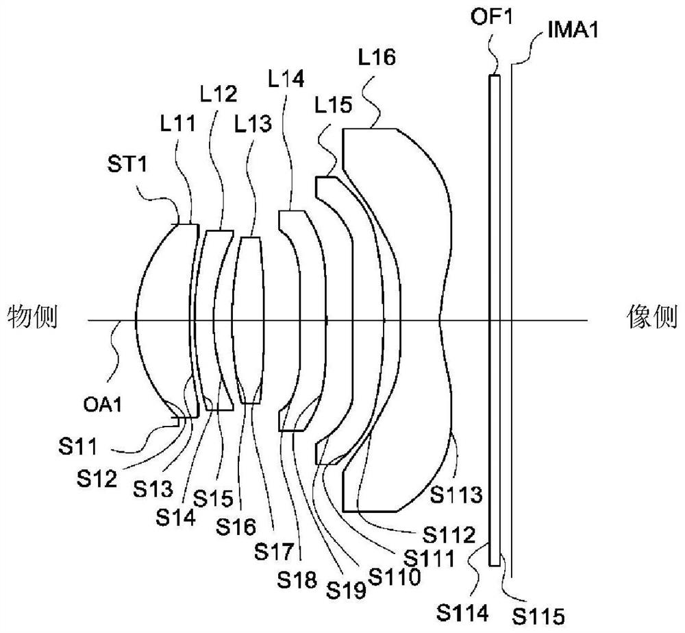
[0048] see figure 1 , figure 1 is a schematic diagram of the lens configuration of the first embodiment of the imaging lens according to the present invention. The imaging lens 1 includes a diaphragm ST1, a first lens L11, a second lens L12, a third lens L13, a fourth lens L14, a fifth lens L15, a sixth lens L16 and Filter OF1. During imaging, the light from the object side is finally imaged on the imaging surface IMA1.
[0049] The first lens L11 is a meniscus lens with positive refractive power. The object side S12 is convex, the image side S13 is concave, and both the object side S12 and the image side S13 are aspheric surfaces.
[0050] The second lens L12 is a meniscus lens with negative refractive power. The object side S14 is convex, the image side S15 is concave, and both the object side S14 and the image side S15 are aspheric surfaces.
[0051] The third lens L13 is a meniscus lens with positive refractive power. The object side S16 is convex, the image side S17 i...
PUM
 Abstract
Description
Claims
Application Information
 - R&D
- Intellectual Property
- Life Sciences
- Materials
- Tech Scout
- Unparalleled Data Quality
- Higher Quality Content
- 60% Fewer Hallucinations
Browse by: Latest US Patents, China's latest patents, Technical Efficacy Thesaurus, Application Domain, Technology Topic, Popular Technical Reports.
© 2025 PatSnap. All rights reserved.Legal|Privacy policy|Modern Slavery Act Transparency Statement|Sitemap|About US| Contact US: help@patsnap.com