Retaining wall earthquake soil pressure time history calculation method based on energy dissipation principle

A technology of energy dissipation and calculation method, applied in the direction of electrical digital data processing, instrumentation, geometric CAD, etc., can solve the problems that the seismic earth pressure cannot be obtained, and the influence of seismic wave earth pressure is not considered.

Active Publication Date: 2020-04-21
SOUTHWEST PETROLEUM UNIV
View PDF6 Cites 1 Cited by
  • Summary
  • Abstract
  • Description
  • Claims
  • Application Information

AI Technical Summary

Problems solved by technology

[0004] Aiming at the above-mentioned deficiencies in the prior art, the present invention provides a time-history calculation method of seismic earth pressure on retaining walls based on the principle of energy dissipation, which solves the problem that traditional earthquake earth pressure calculation assumes that the slip surface is an oblique line and the earthquak

Method used


Image

  • Retaining wall earthquake soil pressure time history calculation method based on energy dissipation principle
  • Retaining wall earthquake soil pressure time history calculation method based on energy dissipation principle
  • Retaining wall earthquake soil pressure time history calculation method based on energy dissipation principle

Examples


Embodiment

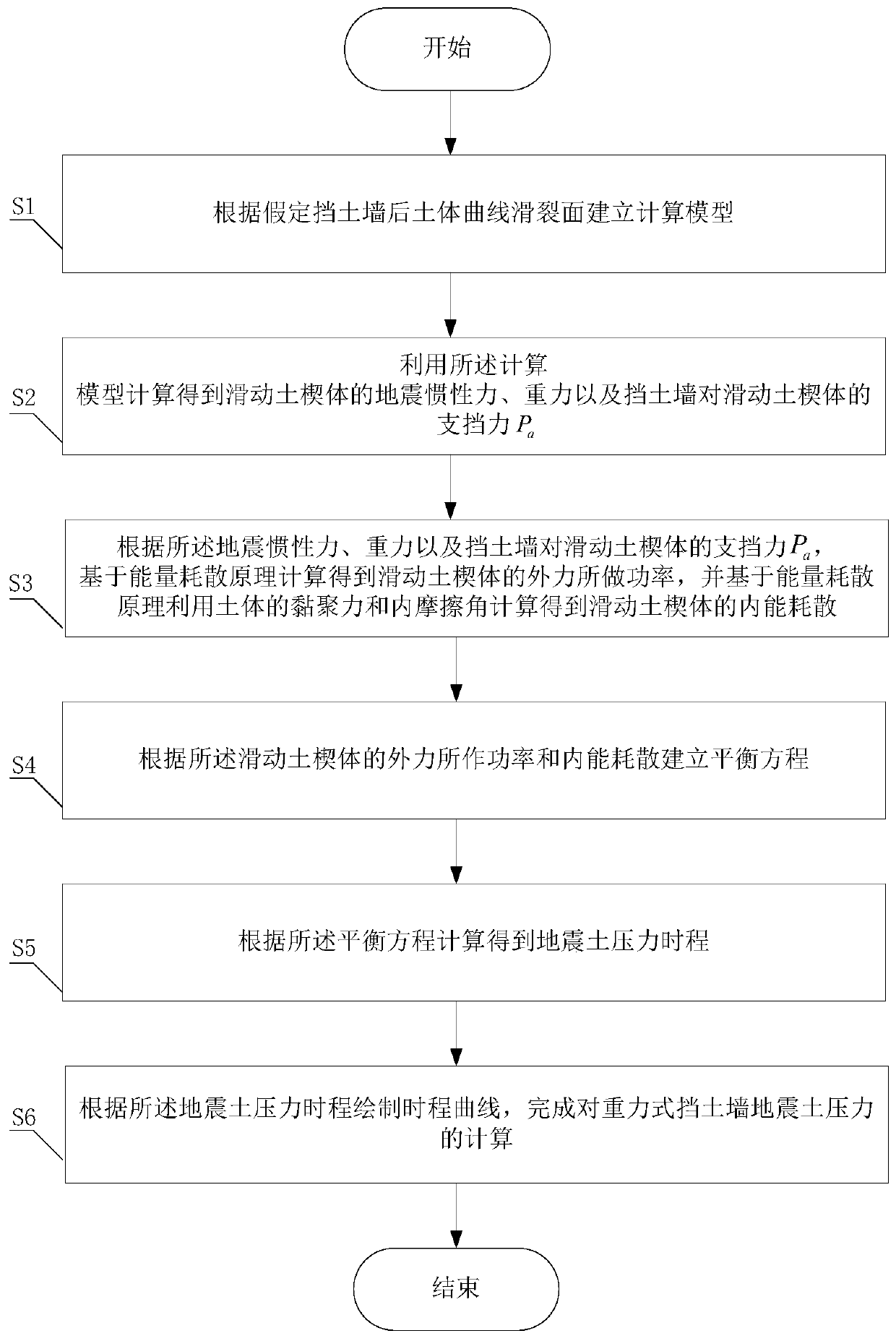
[0064] Such as figure 1 As shown, the present invention discloses a method for calculating time history of seismic earth pressure of retaining wall based on the principle of energy dissipation, which is characterized in that it includes the following steps:

[0065] S1. Establish a calculation model based on the soil curve slip surface behind the retaining wall.

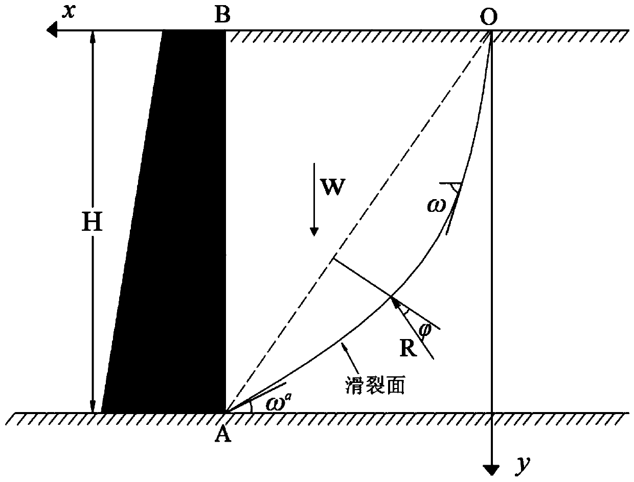
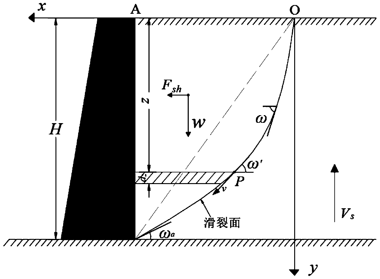
[0066] In this example, when the filling soil behind the retaining wall slides down along the back of the wall and a sliding surface in the filling soil to reach the limit equilibrium state, the sliding surface is not a straight line as proposed by Coulomb's law, but passes through the toe of the wall. curve, and assume that the surface is a cycloid. The present invention assumes that the gravity retaining wall is rigid, and the filling soil behind the wall is cohesive soil, and the specific research model is as follows figure 2 shown. Among them, W is the gravity of the sliding soil wedge, R is the reaction forc...


PUM


Abstract

The invention provides a retaining wall earthquake soil pressure time history calculation method based on an energy dissipation principle. The method comprises the steps of: establishing a calculationmodel to respectively compute the earthquake inertia force and gravity of a sliding soil wedge body and supporting force of the wall to the sliding soil wedge body; based on an energy dissipation principle, respectively calculating to obtain the power and the internal energy dissipation of the external force of the sliding soil wedge body; establishing a balance equation based on an energy conservation principle; calculating and obtaining the maximum time history of the retaining force of the corresponding retaining wall to the sliding soil wedge body under the continuous action of the earthquake, namely the solved earthquake soil pressure time history; and performing drawing to obtain a seismic soil pressure time-history curve. According to the invention, a slip crack surface is supposedto be an oblique straight line in traditional earthquake soil pressure calculation, an earthquake action is simplified into an inertia force with constant magnitude and invariable direction, the influence of earthquake waves on earthquake soil pressure when the earthquake waves are transmitted in a slope body is not considered, most of the obtained earthquake soil pressure is a constant value anddistorted, and a series of problems that how the earthquake soil pressure changes along with time cannot be obtained are solved.

Description

technical field [0001] The invention belongs to the technical field of seismic earth pressure analysis, in particular to a method for calculating time history of earthquake earth pressure on retaining walls based on the principle of energy dissipation. Background technique [0002] Gravity retaining wall has become the most commonly used form of retaining wall due to its simple form, easy local materials and convenient construction. Its characteristic is to maintain the retaining wall under the earth pressure by its own gravity However, the current seismic design of the structure is too simple, and there is no concrete and strong evidence for the safety and economy of the design, and there is a lack of evidence on how the earth pressure of the gravity retaining wall changes with time under the continuous action of earthquakes. Therefore, it is necessary to study the seismic earth pressure time history of gravity retaining walls. [0003] There are some methods for calculati...

Claims


Application Information

Patent Timeline
IPC IPC(8): G06F30/13G06F119/14
Inventor 曲宏略邓媛媛黄雪王晨旭李彪郭亮张哲李博文刘哲言吴昆铭
Owner SOUTHWEST PETROLEUM UNIV
Why Eureka
Try Eureka