
Lifting device for bearing wafer

A technology for carrying wafers and lifting devices, applied in electrical components, semiconductor/solid-state device manufacturing, circuits, etc., and can solve problems such as horizontal movement of wafers

Pending Publication Date: 2020-04-21
NINGBO SEMICON INT CORP
View PDF0 Cites 2 Cited by
  • Summary
  • Abstract
  • Description
  • Claims
  • Application Information

AI Technical Summary

Problems solved by technology

[0004] The purpose of the present invention is to provide a lifting device for carrying wafers, which can solve the problem of horizontal movement of the wafers during the process of being pulled up by glue and falling back in the process of dispensing glue

Method used


Image

  • Lifting device for bearing wafer
  • Lifting device for bearing wafer
  • Lifting device for bearing wafer

Examples


Embodiment Construction

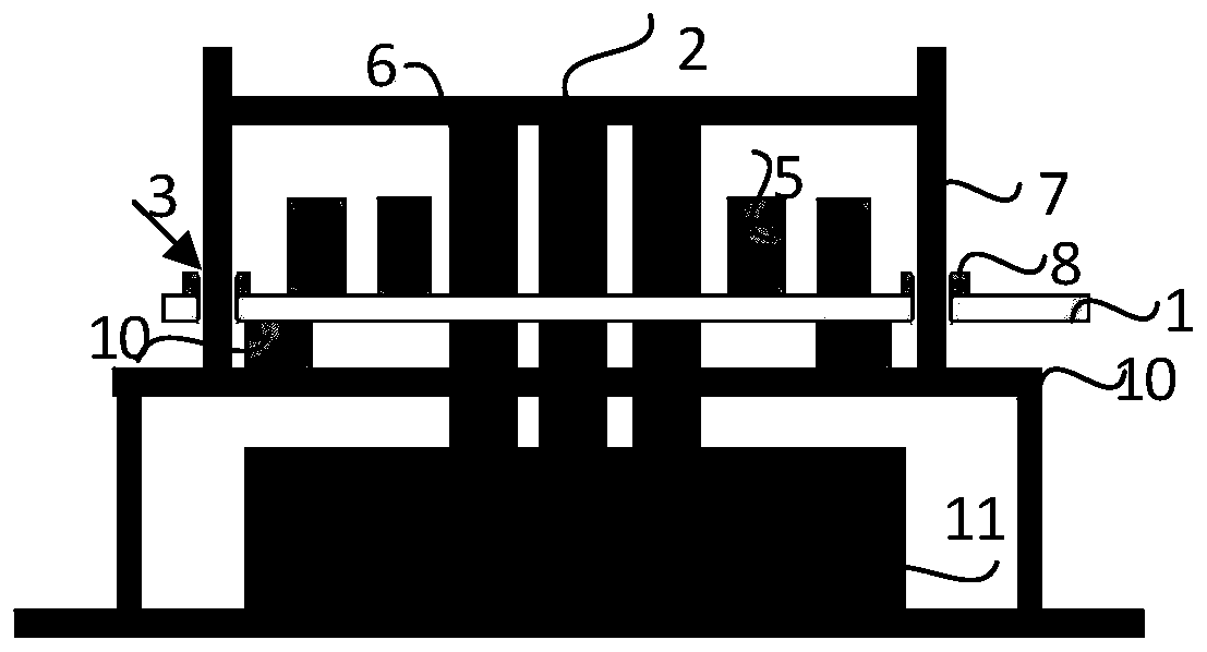
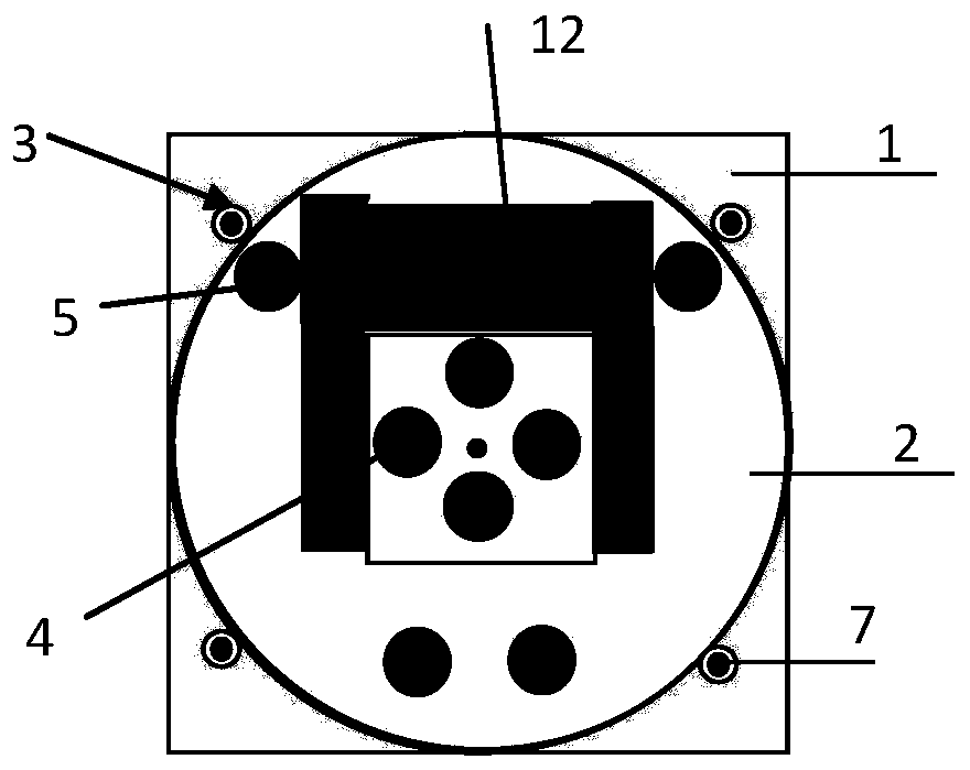
[0020] A lifting device for carrying wafers of the present invention will be further described in detail below in conjunction with the accompanying drawings and specific embodiments. According to the following description and accompanying drawings, the advantages and characteristics of the present invention will be clearer, however, it should be noted that the concept of the technical solution of the present invention can be implemented in many different forms, and is not limited to the specific implementation set forth herein. example. The drawings are all in very simplified form and use imprecise scales, and are only used to facilitate and clearly assist the purpose of illustrating the embodiments of the present invention.

[0021] The terms "first", "second", etc. in the description and claims are used to distinguish between similar elements and not necessarily to describe a specific order or chronological order. It is to be understood that the terms so used are interchang...


PUM


Abstract

The invention discloses a lifting device for bearing a wafer. The lifting device comprises a lifting platform which is used for bearing the wafer and can move up and down, wherein the lifting platformis provided with at least one first through hole and at least one second through hole which penetrate through the lifting platform, at least one first through hole forms an annular shape, the interior of the annular shape can accommodate the horizontally placed wafer, and at least one second through hole is located in the annular shape; a first wafer supporting piece which is located on the uppersurface of the lifting table and in the annular interior; a second wafer supporting piece which penetrates through the lifting table through the second through hole, wherein the lifting table can move up and down along the second wafer supporting piece, when the lifting platform descends, the wafer is supported by the second wafer supporting piece, and when the lifting platform is lifted, the wafer is supported by the first wafer supporting piece; and a limiting structure which penetrates through the lifting table through the first through hole, wherein the upper surface of the limiting structure is higher than the upper surface of the second wafer supporting piece, the lifting table can move up and down along the limiting structure, and the limiting structure surrounds the periphery of the wafer and is used for limiting horizontal movement of the wafer.

Description

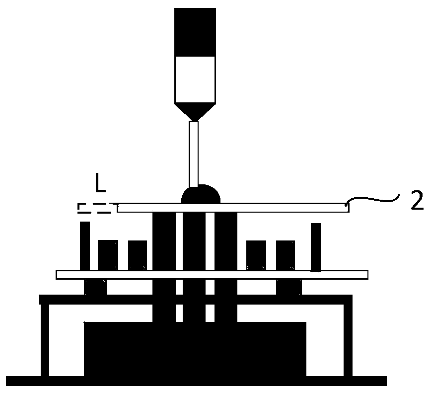
technical field [0001] The invention relates to the field of semiconductor equipment, in particular to a lifting device for carrying wafers. Background technique [0002] Wafer dispensing calibration device, including glue dispenser and calibration table, is mainly used to spray resin glue with accurate weight on the upper surface of process wafer. The viscosity of resin glue is relatively high. When the glue dispenser is dispensing glue, there In the action of pulling up and down, when the pulling force of the adhesive is greater than the gravity of the wafer, the wafer is slightly pulled up, and there is a phenomenon of horizontal displacement of the wafer when the wafer falls back. refer to figure 1 , is a schematic diagram of the structure of the wafer dispensing calibration device in an example, the wafer 2 is shifted to the right, and the shift amount L is shown in the dotted box on the left side of the wafer 2 . [0003] Therefore, how to prevent the horizontal move...

Claims


Application Information

Patent Timeline
IPC IPC(8): H01L21/687
CPCH01L21/68742H01L21/6875
Inventor 汪新学陶智昆
Owner NINGBO SEMICON INT CORP
Learn More