Heat storage device, heat storage system and heat storage method

A heat storage device and a heat storage technology are applied in the field of heat storage systems, which can solve problems such as insufficient heat energy of the heat storage device, and achieve the effects of suppressing the increase in operating costs and reducing energy shortage.

Active Publication Date: 2021-06-29
MITSUBISHI ELECTRIC CORP
View PDF7 Cites 0 Cited by
  • Summary
  • Abstract
  • Description
  • Claims
  • Application Information

AI Technical Summary

Problems solved by technology

[0003] In the case that the demand for heat energy exceeds the supply, there may be insufficient heat energy for the heat storage device

Method used


Image

  • Heat storage device, heat storage system and heat storage method
  • Heat storage device, heat storage system and heat storage method
  • Heat storage device, heat storage system and heat storage method

Examples


Embodiment approach 1

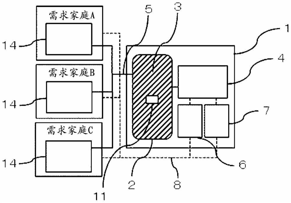
[0031] figure 1 It is a schematic structural diagram showing the heat storage system of Embodiment 1. exist figure 1 In one example, one heat storage device 1 is connected to the demand houses A, B, and C as three different families, and the heat storage system can use one heat storage device 1 to meet the heat demands of different multiple demand houses A, B, and C. way of working. Each required house may be a different family in a multi-family house such as an apartment, or may be a single-family house in a different adjacent building.

[0032] The heat storage device 1 includes a heat storage tank 2 , a heat source unit 4 , a heat transport unit 5 , a heat output prediction unit 6 , a control unit 7 , an information transmission unit 8 , and a stored heat estimation unit 11 . The heat storage device 1 is connected to a heat consumer 14 of a demand house using the heat stored in the heat storage device 1 .

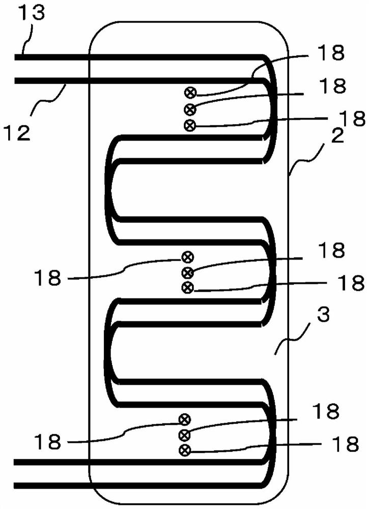
[0033] The heat storage tank 2 is a frame that holds the heat s...

Embodiment approach 2

[0090] use Figure 7 A heat storage system according to Embodiment 2 will be described. Figure 7 It is a schematic structural diagram showing the heat storage system of Embodiment 2. Compared with the thermal storage system of Embodiment 1, the thermal storage system of Embodiment 2 further includes human detection means 9 and weather information collection means 15 . Hereinafter, the heat storage system of Embodiment 2 will be described centering on differences from the heat storage system of Embodiment 1. FIG.

[0091] Human detection means 9, 9, 9 are sensors for detecting the presence or absence of human beings, and are installed in each of the demand houses A, B, and C. The human detection units 9 , 9 , 9 are respectively connected to the control unit 7 and send detection results to the control unit 7 .

[0092] The weather information collection unit 15 is a unit for acquiring weather information, and is connected to the control unit 7 . The weather information coll...

Embodiment approach 3

[0098] use Figure 8 A thermal storage system according to Embodiment 3 will be described. Figure 8 It is a schematic cross-sectional view in the vertical direction of the heat storage tank 2 according to the third embodiment. Compared with the heat storage system of Embodiment 1, the heat storage system of Embodiment 3 is equipped with the water level gauge 19 instead of the temperature sensor 18 . Hereinafter, the heat storage system of Embodiment 3 will be described centering on differences from the heat storage system of Embodiment 1. FIG.

[0099] The heat storage tank 2 included in the heat storage system according to Embodiment 3 is a frame holding a heat storage material 3 inside. The heat storage material 3 held in the heat storage tank 2 is a member that causes a phase change between liquid and solid. Such as Figure 8 As shown, the heat storage tank 2 according to Embodiment 3 includes a water level gauge 19 for measuring the water level of the heat storage mat...


PUM


Abstract

The present invention provides a heat storage device, a heat storage system, and a heat storage method capable of suppressing an increase in running cost, preventing energy shortage even when heat extraction is progressing, and reducing heat radiation loss. The heat storage device includes: a heat storage tank containing a heat storage material having heat storage performance and heat release performance; a heat source unit that generates heat supplied to the heat storage material; A first heat medium flow path, the first heat medium flow path is used for the flow of the first heat medium, and is thermally connected with the heat storage material and the heat source machine; and a plurality of temperature sensors, the plurality of temperature sensors are arranged in the heat storage tank , and measure the temperature of the heat storage material. The plurality of temperature sensors are arranged at positions at different distances from the heat transfer surface of the first heat medium flow path where the first heat medium flow path and the heat storage material come into contact. The heat source machine generates heat based on the detection results of the plurality of temperature sensors.

Description

technical field [0001] The present invention relates to a heat storage device for storing heat energy, a heat storage system and a heat storage method using the heat storage device. Background technique [0002] Conventionally, heat storage devices that store thermal energy are known. The heat storage device includes, for example, a heat storage material that can temporarily store heat in a tank and use it when necessary. The heat storage material can be used for heat exchange by the user supplying heat to the heat storage material and storing it, or taking heat from the heat transfer surface of the heat storage material and taking it out. For example, a user uses a heat storage device to fill a time gap between demand and supply of thermal energy through heat exchange. [0003] When the demand for heat energy exceeds the supply, there may be a shortage of heat energy in the heat storage device. Therefore, a thermal storage system has been proposed that operates a heat so...

Claims


Application Information

Patent Timeline
Patent Type & Authority Patents(China)
IPC IPC(8): F28D20/00F28D20/02
CPCF28D20/00F28D20/02F28D20/0034F28D20/0056F28D20/021F28F27/00F24D11/0207F24D19/1006Y02B30/17Y02E60/14F28D20/028
Inventor 铃木俊圭一法师茂俊米田典宏臼田雄一丸山诚司矢次庆和野村泰光中园纯一
Owner MITSUBISHI ELECTRIC CORP
Why Eureka
Try Eureka