Pressure buffer device and regenerative combustion type exhaust gas treatment device including the pressure buffer device

A technology of processing device and buffer device, applied in the direction of pipes/pipe joints/pipe fittings, mechanical equipment, pipe components, etc., can solve the problems of overall large-scale equipment, increased processing capacity, increased power consumption, etc., to reduce operating costs. added effect

Active Publication Date: 2017-08-25
CHUGAI RO CO LTD
View PDF6 Cites 0 Cited by
  • Summary
  • Abstract
  • Description
  • Claims
  • Application Information

AI Technical Summary

Problems solved by technology

[0016] However, in the former method, since a large pressure loss occurs in the duct, a fan with a large power is required, which has the problem of increasing power consumption.
In addition, for the latter of the above-mentioned methods, since the gas to be processed is diluted by using the atmosphere, the processing amount of the gas to be processed will increase, resulting in the combustion chamber 3, regenerators 5A, 5B, 5C As a result of the increase in scale of ancillary equipment such as

Method used


Image

  • Pressure buffer device and regenerative combustion type exhaust gas treatment device including the pressure buffer device
  • Pressure buffer device and regenerative combustion type exhaust gas treatment device including the pressure buffer device
  • Pressure buffer device and regenerative combustion type exhaust gas treatment device including the pressure buffer device

Examples


Embodiment Construction

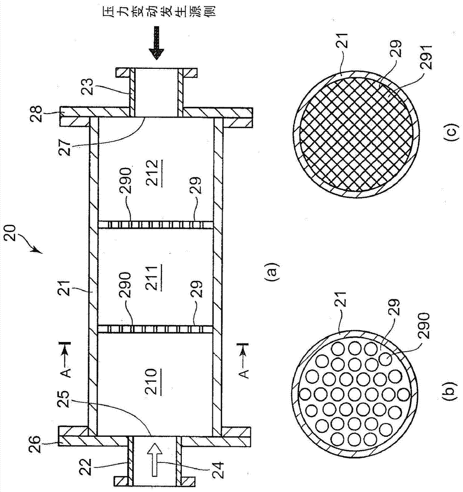
[0054] Hereinafter, a pressure buffer device according to an embodiment of the present invention will be described with reference to the drawings. In the following description, words indicating directions and positions (such as "upstream" or "downstream") are used for convenience of description, they are used to make the invention easy to understand, and do not limit the technical scope of the present invention because of the meaning of these words. Generate restrictions. In addition, the following description is only one embodiment of the present invention, and is not intended to limit the applicable objects or uses of the present invention.

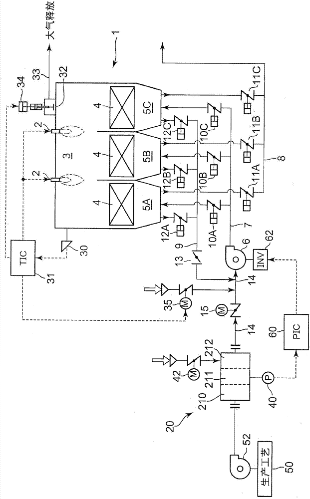
[0055] The pressure buffer device according to the embodiment of the present invention is installed between a pipe (both not shown) connecting a fluid supply source and a treatment device that processes the fluid, and compensates for fluid pressure fluctuations in the pipe due to the operation of the treatment device. to absorb.

[00...


PUM


Abstract

The invention provides a pressure buffering device which can effectively absorb fluid pressure change generated in a pipe under the action of a treating device without increasing the pressure loss of the pipe connecting a fluid supply source to the treating device for treating the fluid. Besides, the invention provides a regenerative combustion type waste gas treating device which comprises the pressure buffering device and inhibits the increase of operation cost and the integral large size of equipment. The pressure buffering device comprises a chamber having a certain volume and including an inlet pipe and an output pipe at two ends; and perforation plates dividing the interior of the chamber into a plurality of spaces and having a plurality of punching holes or screen holes formed thereon. The interior of the chamber is divided into a plurality of pressure buffering chambers by the perforation plates arranged at specified intervals relative to the flowing direction of fluid, and pressure detecting elements for detecting inner pressures of the pressure buffering chambers are arranged in the central pressure buffering chambers other than the pressure chamber at the most upstream side and the pressure chamber at the most downstream side in the flowing direction of the fluid. The pressure buffering device is preferred to be arranged in the regenerative combustion type waste gas treating device as an example of treading devices.

Description

technical field [0001] The invention relates to a pressure buffer device arranged between a pipeline connecting a fluid supply source and a treatment device for treating the fluid, and a thermal storage combustion waste gas treatment device comprising the pressure buffer device. Background technique [0002] Exhaust gas containing volatile organic compounds (V°C) from painting factories etc. is subject to emission restrictions. In these plants, when decomposing exhaust gas containing VOCs, for example, using Image 6 The shown regenerative combustion type exhaust gas treatment device 1' (for example, refer to Patent Document 1). [0003] The above-mentioned regenerative combustion type exhaust gas treatment device 1' is composed of a combustion chamber 3, three regenerator chambers (5A, 5B, 5C), a gas to be treated supply pipe 7 (gas to be treated supply flow path), a gas to be treated exhaust pipe 8 ( Process gas exhaust flow path) and purge gas extraction pipe 9 (purge ga...

Claims


Application Information

Patent Timeline
Patent Type & Authority Patents(China)
IPC IPC(8): F16L55/04F16L55/02F23G7/06
CPCF16L55/02718F16L55/04F23G7/06
Inventor 村元俊博
Owner CHUGAI RO CO LTD
Why Eureka
Try Eureka