Air gun strip nail stamping die

A technology of stamping die and air gun, applied in the field of air gun row nail processing and forming, can solve the problems of easy disengagement, sheet falling off, unstable positioning, etc., and achieve the effect of increasing stability and firmness, and increasing resistance area.

Active Publication Date: 2020-04-24
佛山市顺德区生昌塑料实业有限公司
View PDF6 Cites 0 Cited by
  • Summary
  • Abstract
  • Description
  • Claims
  • Application Information

AI Technical Summary

Problems solved by technology

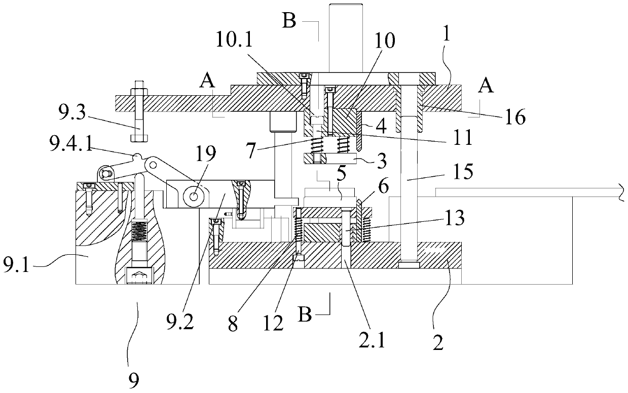
[0003] After the nail strip cutting device in the prior art cuts the strip nail material, all the strip nails are formed in a straight line, that is, the outer diameters of both ends of the strip nails are the same. When the plate is packaged, its positioning is unstable. Since there is no limit at the tail of the nail, the plate will fall off, especially where it is under pressure, it is more likely to be disengaged, which will affect the service life.

Method used


Image

  • Air gun strip nail stamping die
  • Air gun strip nail stamping die
  • Air gun strip nail stamping die

Examples


Embodiment Construction

[0023] The present invention will be further described below in conjunction with the accompanying drawings and specific embodiments.

[0024] In the description of the present invention, it should be noted that the orientation or positional relationship indicated by the terms "upper and lower", "upper end", "lower end", "end", "outside" etc. is based on the orientation or positional relationship shown in the drawings , is only for the convenience of describing the present invention and simplifying the description, but does not indicate or imply that the referred device or element must have a specific orientation, be constructed and operated in a specific orientation, and thus should not be construed as limiting the present invention. In addition, the terms "first", "second", and "third" are only used for descriptive purposes, for distinguishing from each other, and should not be understood as indicating or implying relative importance.

[0025] In the description of the presen...


PUM


Abstract

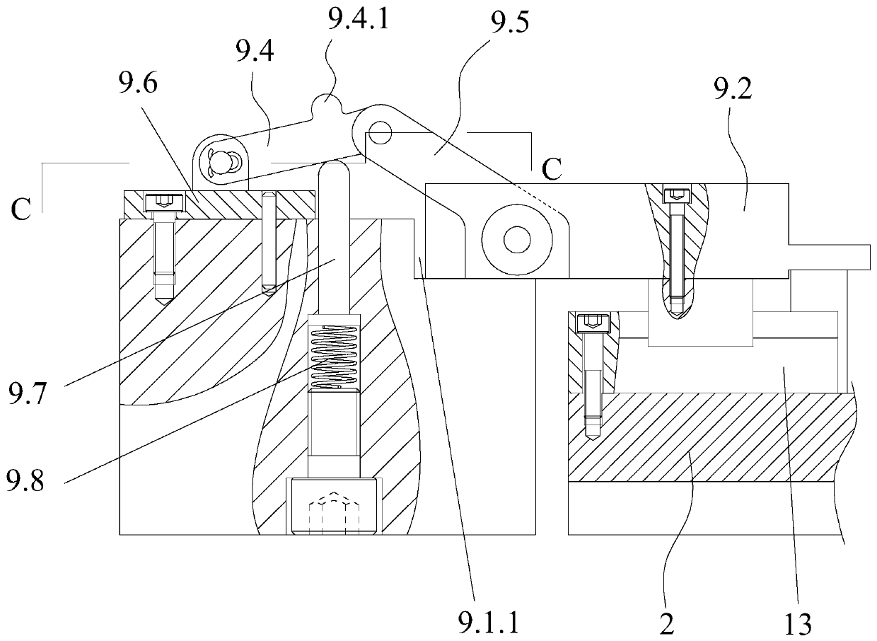
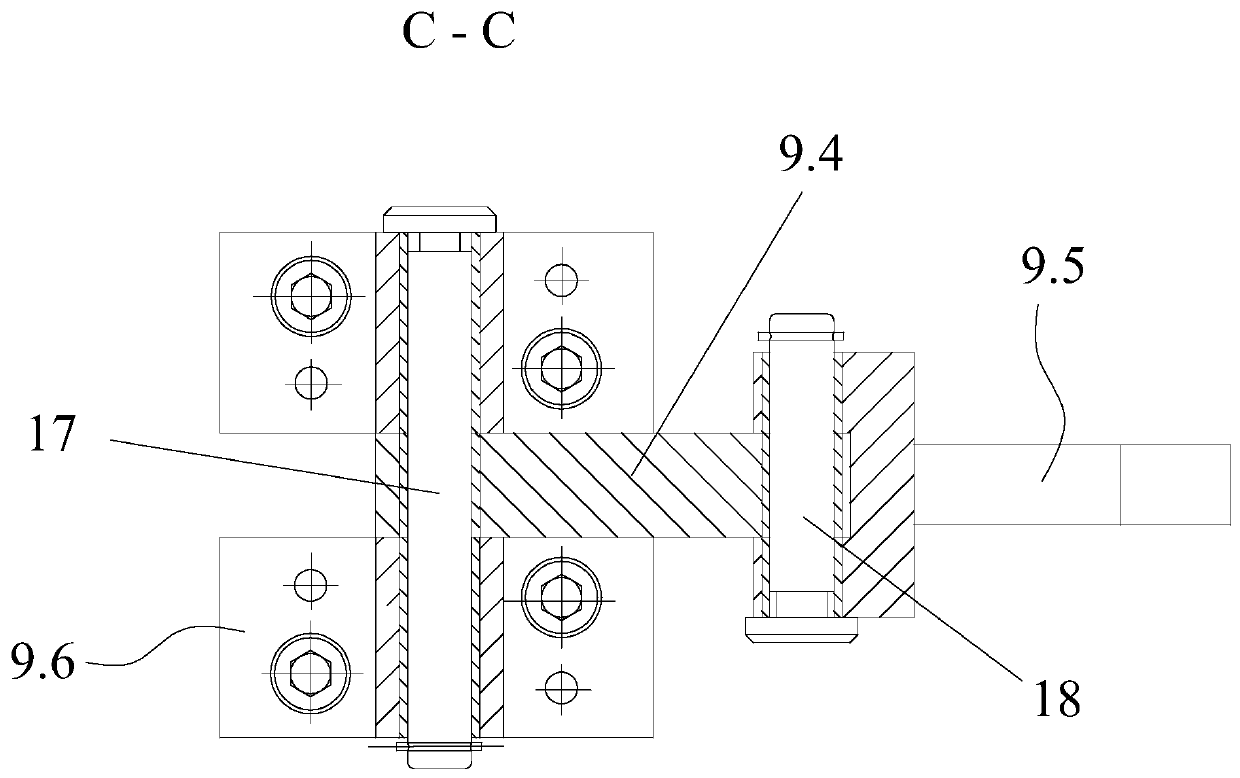
The invention discloses an air gun strip nail stamping die. The die comprises an upper die plate and a lower die plate, an upper pressing plate and an upper blade are arranged on the upper die plate,a positioning bottom plate and a lower blade which are in one-to-one correspondence with the upper pressing plate and the upper blade are arranged on the lower die plate; the upper pressing plate andthe upper die plate can relatively move in the vertical direction, a first buffer element is arranged between the upper pressing plate and the upper die plate, the positioning bottom plate and the lower die plate can relatively move in the vertical direction, and a second buffer element is arranged between the positioning bottom plate and the lower die plate. The die also comprises a cold headingmechanism, which is used for upsetting the end face of the side, deviating from the blanking end, of a strip nail blanking piece, and the end of the strip nail is promoted to deform to form a limitingpart. According to the air gun strip nail stamping device, after the strip nail is blanked and cut off, the tail of the strip nail is subjected to upsetting treatment, so that the tail of the strip nail is provided with a limiting part.

Description

technical field [0001] The invention relates to the technical field of air gun nail removal processing and molding, in particular to an air gun nail removal stamping die. Background technique [0002] Row nails, also called code nails, are packaging products used in automatic box sealing and bookbinding industries. They are used in conjunction with nail guns to achieve packaging operations. Its structure is a row of nails arranged side by side and installed in the nail gun. , The nails are sequentially driven out and fixed on the packaged items through a nail gun. During production and processing, generally a plurality of metal wires are brought together to form a side-by-side arrangement state, and then glued through glue, and then the glue is dried, so that the side-by-side metal wires form an integrated state, and finally the The juxtaposed metal strips composed of metal wires are cut to form row nails of different specifications. [0003] After the nail strip cutting d...

Claims


Application Information

Patent Timeline
Patent Type & Authority Applications(China)
IPC IPC(8): B21G3/00B21G3/12B21G3/18B21G3/20
CPCB21G3/005B21G3/12B21G3/18B21G3/20
Inventor 刘康
Owner 佛山市顺德区生昌塑料实业有限公司
Why Eureka
Try Eureka