Three-way valve, compressor assembly, refrigerating device and control method of refrigerating device

A technology for a refrigeration device and a compressor is applied in the fields of refrigeration devices and their control, compressor components, and three-way valves, which can solve problems such as failure to return to normal, refrigeration system failure, and three-way valves that cannot work normally, so as to shorten the restart time. time, productivity, convenience and reliability

Pending Publication Date: 2020-04-24
GUANGDONG MEIZHI PRECISION MFG
View PDF10 Cites 1 Cited by
  • Summary
  • Abstract
  • Description
  • Claims
  • Application Information

AI Technical Summary

Problems solved by technology

However, the three-way valve depends on the effect of high and low pressure differences. When there is no pressure difference in the system or the system pressure difference is lower than

Method used


Image

  • Three-way valve, compressor assembly, refrigerating device and control method of refrigerating device
  • Three-way valve, compressor assembly, refrigerating device and control method of refrigerating device
  • Three-way valve, compressor assembly, refrigerating device and control method of refrigerating device

Examples


Embodiment 1

[0084] The refrigeration device includes: a compressor assembly, a first heat exchanger, a second heat exchanger, a throttling assembly, and the like.

[0085] Among them, such as Figure 9As shown, the compressor assembly includes: a compressor 50, a three-way valve 100 and an accumulator 60, etc., the compressor 50 is a rotary compressor 50, the compressor 50 includes a housing, a motor assembly and a compression assembly, and the housing defines In the accommodating space, the motor assembly and the compression assembly are located in the accommodating space, and the casing has an exhaust port 510 and an air return port 520 communicating with the inner space. The exhaust port 510 is provided with an exhaust pipe, and the accommodating space and the exhaust pipe together constitute the high-pressure side of the compressor assembly.

[0086] The liquid accumulator 60 is located outside the casing, and the liquid accumulator 60 communicates with the air return port 520 of the...

Embodiment 2

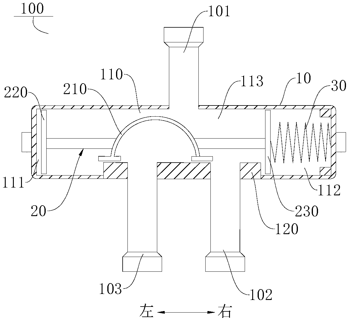
[0102] Such as Figure 5 and Figure 6 As shown, the difference from the first embodiment is that the elastic member 30 is disposed in the first chamber 111 . When there is no pressure difference or a small pressure difference between the two ends of the valve core 20, under the action of the elastic restoring force of the elastic member 30, the elastic member 30 can pull the valve core 20 to be in the first position.

Embodiment 3

[0104] Such as Figure 7 and Figure 8 As shown, the difference from Embodiment 1 is that in this embodiment, in this embodiment, the elastic member 30 includes a first elastic member 310 and a second elastic member 320, and the first elastic member 310 is located in the first chamber In 111 , the second elastic member 320 is disposed in the second chamber 112 . When there is no pressure difference or a small pressure difference between the two ends of the spool 20, under the action of the elastic restoring force of the first elastic member 310 and the second elastic member 320, the first elastic member 310 and the second elastic member 320 cooperate to normally The driving spool 20 moves toward the first position.


PUM


Abstract

The invention discloses a three-way valve, a compressor assembly, a refrigerating device and a control method of the refrigerating device. The three-way valve comprises a valve body, a valve element,an elastic piece and a pilot valve. The valve body is provided with a cavity, an inlet, a first outlet and a second outlet; the inlet, the first outlet and the second outlet communicate with the cavity; the inlet communicates with the first outlet and the second outlet in a switching mode; the valve element is provided with a first position enabling the inlet to communicate with the first outlet and a second position enabling the inlet to communicate with the second outlet; the elastic piece constantly drives the valve element to move towards the first position, and the pilot valve drives thevalve element to move towards the second position. According to the three-way valve for a compressor, the elastic piece is arranged in the valve body, the valve element can be normally driven to resetto the first position under the action of the elastic restoring force of the elastic piece, and thus the inlet and the first outlet of the three-way valve can be kept in a communicating state withoutpressure difference or when the pressure difference is small, and the running reliability and stability of the three-way valve are improved. In addition, the pilot valve can conveniently drive the valve element to be switched to the second position.

Description

technical field [0001] The invention relates to the technical field of refrigeration equipment, in particular to a three-way valve, a compressor assembly, a refrigeration device and a control method thereof. Background technique [0002] In a refrigeration device, when the compressor is stopped after running and can be restarted, the pressure difference between the suction side and the discharge side of the compressor must reach a certain range before it can be restarted, especially for large amounts of refrigerant. For a system equipped with a rotary compressor, the pressure difference must reach a small value (for example, 1kgf / cm 2 ), otherwise the compressor will not be able to start, so that the function of quick restart after shutdown cannot be realized. [0003] On the other hand, when the compressor stops, the refrigerant in the high-pressure side heat exchanger will return to the low-pressure side through the gap of the compressor components, thereby increasing the...

Claims


Application Information

Patent Timeline
IPC IPC(8): F16K11/02F25B41/04F25B49/02F25B41/20
CPCF16K11/02F25B49/02F25B41/20
Inventor 熊溢威高斌李华明
Owner GUANGDONG MEIZHI PRECISION MFG
Why Eureka
Try Eureka