
Fixed mounting seat for power transformer

A technology of power transformer and mounting seat, which is applied in the direction of transformer/reactor installation/support/suspension, etc. It can solve problems such as potential safety hazards, looseness of power transformers, and inability to adjust, so as to reduce stress, avoid safety problems, and expand use range effect

Active Publication Date: 2020-04-24
STATE GRID SHANDONG ELECTRIC POWER CO BOXING POWER SUPPLY CO
View PDF4 Cites 1 Cited by
  • Summary
  • Abstract
  • Description
  • Claims
  • Application Information

AI Technical Summary

Problems solved by technology

[0003] The purpose of the new invention is to solve the problem that the power transformer fixing seat cannot adjust the transverse span of the mounting plate in the prior art, and can not adjust the transverse span according to the actual needs of the transformer, which reduces the use range of the power transformer fixing seat, and the power transformer and installation There is no defensive positioning mechanism at the connection between them, and the positioning is only fixed by bolts. When the bolts are damaged due to force during production, the power transformer may become loose with the mounting plate, which has the disadvantage of safety hazard. A fixed mount for power transformers

Method used


Image

  • Fixed mounting seat for power transformer
  • Fixed mounting seat for power transformer
  • Fixed mounting seat for power transformer

Examples


Embodiment Construction

[0020] The following description is for disclosing the novelty of the present invention so that those skilled in the art can realize the novelty of the present invention. The preferred embodiments described below are only examples, and those skilled in the art can devise other obvious variations.

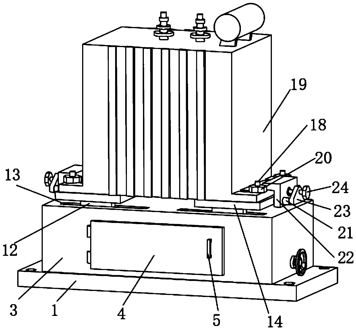
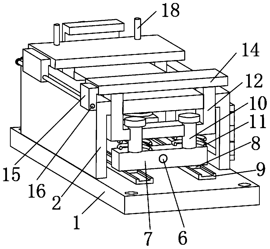
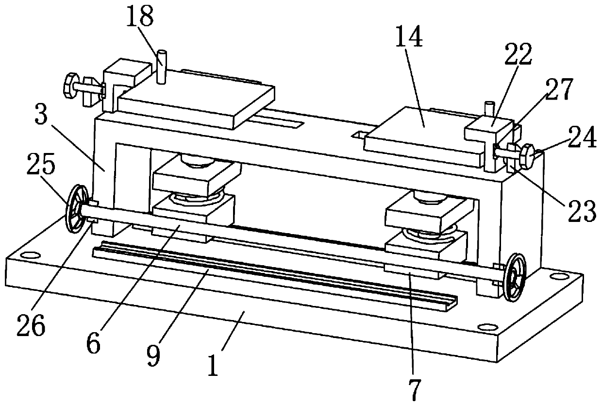
[0021] Such as Figure 1-4 Shown includes bottom plate 1, four connecting holes 2 are opened on the top of bottom plate 1, and four connecting holes 2 are evenly distributed at the four corners of the top of bottom plate 1, and the top of bottom plate 1 is fixedly connected with shielding shell 3, and the front of shielding shell 3 It is connected with an openable sealing mechanism. The openable sealing mechanism includes a maintenance door 4. The front of the maintenance door 4 is connected with a handle 5 through a screw thread. By setting the connection hole 2, it is convenient to insert bolts and other fixing parts to secure the bottom plate 1. The effect of fixed installation ...


PUM


Abstract

The invention relates to the technical field of power transformer mounting seats, and in particular relates to a fixed mounting seat for a power transformer. The device comprises a bottom plate. The top of the bottom plate is fixedly connected with a shielding shell, and the front surface of the shielding shell is connected with an openable sealing mechanism. A bidirectional screw rod is rotated by a turntable. Two symmetrical and opposite external threads of the bidirectional screw rod can drive two moving plates to move in the same direction or in the opposite directions. Mounting plates atthe top of a U-shaped fixing frame are synchronously driven to synchronously move, so that the purpose of adjusting the span between the two mounting plates is achieved. Adjustment can be convenientlycarried out according to the actual size of the power transformer body, and the application range of the power transformer fixing seat is expanded. An L-shaped positioning end is moved to the top ofthe fixing position of the power transformer body through a pushing mechanism, and the L-shaped positioning end can play a role in positioning. Stress of a fixing threaded sleeve and a threaded rod isreduced. The safety problem caused by falling is avoided, and the defense effect is achieved.

Description

technical field [0001] The invention relates to the technical field of power transformer mounting bases, in particular to a fixed mounting base for power transformers. Background technique [0002] In the patent document with the publication number CN108831684A in the prior art, the present invention discloses a power transformer fixing device, which includes a mounting plate, the top of the mounting plate is fixedly connected with a shock absorbing box, and the two sides of the bottom of the inner wall of the shock absorbing box Both are fixedly connected with a telescopic rod, the top of the telescopic rod is fixedly connected with a supporting plate, the surface of the telescopic rod is covered with a first spring, and the bottom of the first spring is fixedly connected with the bottom of the inner wall of the shock absorbing box. The power transformer fixing seat cannot adjust the lateral span of the mounting plate, and cannot be adjusted according to the actual need of ...

Claims


Application Information

Patent Timeline
Patent Type & Authority Applications(China)
IPC IPC(8): H01F27/06
CPCH01F27/06
Inventor 崔凤霞孔文超潘猛张肖肖李娟孙海辉曹宁宁刘健巩秀萍
Owner STATE GRID SHANDONG ELECTRIC POWER CO BOXING POWER SUPPLY CO
Learn More