Laser projection television

A technology of laser projection and laser TV, applied in the field of laser projection, can solve the problems of cumbersome and difficult adjustment of laser TV

Pending Publication Date: 2020-04-24
QINGDAO HISENSE LASER DISPLAY CO LTD
View PDF7 Cites 6 Cited by
  • Summary
  • Abstract
  • Description
  • Claims
  • Application Information

AI Technical Summary

Problems solved by technology

[0005] The purpose of the present invention is to provide a laser projection TV, which solves the technical problem that the existing laser TV is difficult and cumbersome to adjust after it moves

Method used


Image

  • Laser projection television
  • Laser projection television
  • Laser projection television

Examples


Embodiment 1

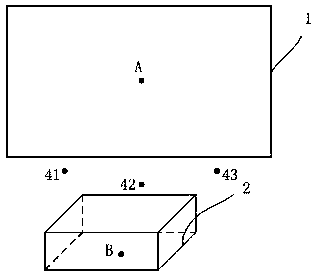
[0030] like Figure 4 As shown, the laser TV proposed by the present invention includes a position detection module 22, which is used to detect the placement position of the laser TV 2, and generates a repositioning reminder signal when its placement position changes relative to the second position B; the position detection module is fast 22 For example, acceleration sensors, gyroscopes and other settings that can detect whether the status of the laser TV 2 changes.

[0031] Or, the laser TV includes a degree of fit detection module 23, which is used to detect the degree of fit between the picture projected by the laser TV 2 and the projection screen 1, and generates a repositioning reminder signal when the degree of fit exceeds a threshold; the degree of fit detection module 23 such as a camera The equipment, by taking pictures of the projection screen on the projection screen 1, analyzes the relationship between the projection screen and the projection screen through image p...

Embodiment 2

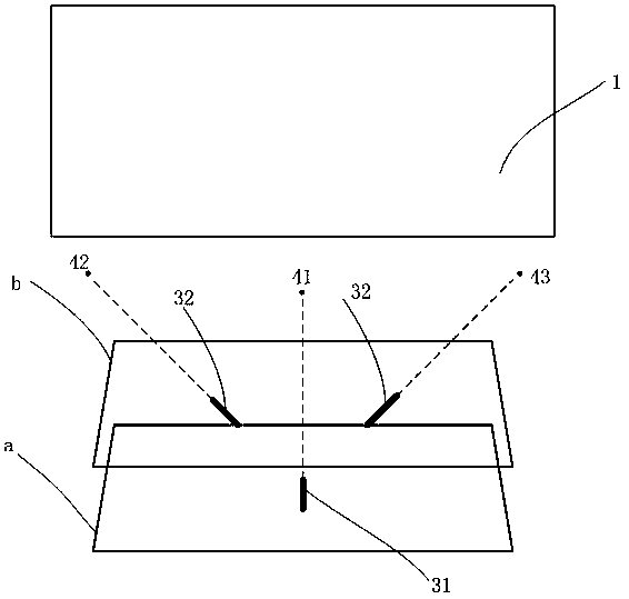
[0035] like Figure 8 As shown, the location detection module 24 includes a camera unit 241 and a location detection unit 242; the camera unit 241 acquires images of light spots formed by the first laser lamp 31, the second laser lamp 32 and the third laser lamp 33 on the side of the projection screen 1 The positioning detection unit 242 judges the coincidence relationship between the light point and the first reference point 41, the second reference point 42 and the third reference point 43 based on the image of the light point, and generates a repositioning reminder signal when the light point does not coincide with the reference point .

Embodiment 3

[0037] In this embodiment, the first reference point 41, the second reference point 42, and the third reference point 43 are marked with reflective materials; Figure 9 As shown, the positioning detection module includes a reflection receiving unit 243 and a reflection detection unit 244. The reflection receiving unit 243 is used to receive the laser light emitted by the first laser lamp 31, the second laser lamp 2, and the third laser lamp 33 by the first reference point 41. , the reflected light reflected by the second reference point 42 and the third reference point 43; the reflection detection unit 244 is used to judge the first laser light 31, the second laser light 32 and the third laser light based on the reflected light received by the reflection receiving unit 243 The light spots formed by the laser light emitted by the lamp 33 on the side of the projection screen coincide with the first reference point 41, the second reference point 42, and the third reference point 4...


PUM


Abstract

The present invention discloses a laser projection television. The laser projection television comprises a projection screen, a laser television body, a first plane, a second plane, a first laser lamp, a second laser lamp, a third laser lamp and a positioning module, wherein the first plane and the second plane are arranged in parallel. The first laser lamp is arranged on the first plane in a manner of being perpendicular to the projection screen, and a light spot formed by laser emitted by the first laser lamp is marked as a first reference point; the second laser lamp and the third laser lamp are both arranged on the second plane and arranged on the two sides of the first laser lamp at a set angle relative to the first laser lamp, and light spots formed by lasers emitted by the second laser lamp and the third laser lamp are marked as a second reference point and a third reference point respectively. When the position of the laser television changes relative to the second position, the positioning module turns on the three laser lamps, when three light spots formed by lasers emitted by the three laser lamps coincide with the three reference points respectively, the laser television is reset to the second position, and the technical problems that after an existing laser television moves, adjustment is difficult and tedious are solved.

Description

technical field [0001] The invention belongs to the technical field of laser projection, and in particular relates to a laser projection TV. Background technique [0002] As an ultra-short-focus product, laser TV can project a 75-100-inch screen. After a user purchases a laser projection TV, professionals will come to install the projection screen 1, such as figure 1 As shown, and adjust the position of the laser TV 2 so that the edge of the projection screen of the laser TV 2 coincides with the projection screen 1, that is, when the projection screen 1 is fixed, the laser TV 2 has an optimal placement position and the projection screen 1 match. [0003] There is a disadvantage in the placement of laser TVs: for cleaning and other similar reasons, the placement of laser TVs will change; and in the case of a fixed screen, the match between the laser TV picture and the screen depends entirely on the position of the laser TV , The position of the laser TV changes, which will...

Claims


Application Information

Patent Timeline
Patent Type & Authority Applications(China)
IPC IPC(8): H04N9/31G03B21/20
CPCH04N9/3161G03B21/2033
Inventor 魏伟达王瑾瑾
Owner QINGDAO HISENSE LASER DISPLAY CO LTD
Why Eureka
Try Eureka