
Flexible clamp for pipe fitting welding and adjusting method thereof

A flexible fixture, pipe fitting welding technology, applied in welding equipment, auxiliary welding equipment, welding/cutting auxiliary equipment, etc., can solve the problem of long fixture production cycle, increased difficulty in tooling management, and welding slag falling between grooves or holes. Medium problem, to shorten the production preparation cycle and production cost, improve the scope of use and flexibility, and solve the difficulty of tooling management

Inactive Publication Date: 2011-04-06
JIANGSU UNIV OF SCI & TECH
View PDF7 Cites 18 Cited by
  • Summary
  • Abstract
  • Description
  • Claims
  • Application Information

AI Technical Summary

Problems solved by technology

Although this kind of special welding fixture ensures the positioning accuracy, it also causes a series of problems, such as long fixture production cycle, repeated capital investment, large space for storage after use, small use range, simplification of functions, and difficulty in tooling management. increase etc.
Traditional flexible welding fixtures generally use grooves or grids with holes to achieve flexible positioning and clamping, but the defect is that welding slag generated by welding will fall between grooves or holes, not only It will affect the position adjustment of the adjustment mechanism and reduce the service life of the fixture components; and continuous position adjustment cannot be achieved, resulting in low production efficiency

Method used


Image

  • Flexible clamp for pipe fitting welding and adjusting method thereof
  • Flexible clamp for pipe fitting welding and adjusting method thereof
  • Flexible clamp for pipe fitting welding and adjusting method thereof

Examples


Embodiment Construction

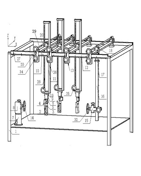
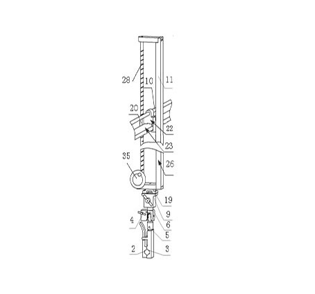
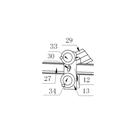
[0018] Such as Figure 1-3 As shown, the pipe welding flexible fixture includes a base support 1, the bottom of which is a fixed-end flange around the Z-axis angle adjustment mechanism 7 and a fixed-end flange around the Y-axis angle adjustment mechanism 8, and the fixed-end flange around the Y-axis angle adjustment mechanism 8. The Y-axis angle adjustment mechanism 8 is connected with a flange rotation mechanism 14 for equally dividing chute. The upper part of the base bracket 1 is provided with a top Y-direction displacement adjustment mechanism 10 for adjusting pipe fittings, a vertical Z-direction displacement adjustment mechanism 11, a top X-direction displacement adjustment mechanism 12, and a flange Y-direction displacement adjustment mechanism 18 for adjusting flanges; The direction displacement adjustment mechanism 10 is perpendicular to the vertical Z direction displacement adjustment mechanism 11 . Wherein, the top Y-direction displacement adjustment mechanism 10 h...


PUM


Abstract

The invention discloses a flexible clamp for pipe fitting welding between multi-section pipe fittings and between a pipe fitting and a flange, and an adjusting method thereof. The bottom of a base bracket is provided with a fixed end flange around Z-axis angle adjusting mechanism and a fixed end flange around Y-axis angle adjusting mechanism connected with an equant chute flange plate rotating mechanism; a top Y-direction displacement regulating mechanism, a vertical Z-direction displacement regulating mechanism and a top X-direction displacement regulating mechanism for regulating the pipe fittings and a flange Y-direction displacement regulating mechanism for regulating the flange are arranged on the upper part of the base bracket; and each mechanism is adjusted to make a positioning mechanism rotate around the X, Y and Z directions. The invention can be rapidly and accurately adjusted and positioned so as to clamp the pipe fittings according to diversified space trends of different pipe fittings, and a set of clamp can adapt to welding a series of pipe fitting sections in different specifications.

Description

technical field [0001] The invention relates to a flexible welding fixture for pipe fittings, in particular to a welding fixture used between multi-section pipe fittings and between pipe fittings and flanges. Background technique [0002] With the rapid development of industrial production, the number of various pipe fittings is increasing, among which welding is the most commonly used and the largest number of connection methods. The trend is more complicated, and sometimes it is very difficult to clearly express its spatial position with drawings. When producing pipe fittings, it is also necessary to design and manufacture fixtures without complete product drawings, that is, tooling without drawings. At present, for the welding of pipe fittings that are diversifying in many spaces, special welding fixtures are generally used, that is, welding support right-angle blocks for certain types of pipe fittings on the table and columns for placing welding flanges can be quickly p...

Claims


Application Information

Patent Timeline
Patent Type & Authority Applications(China)
IPC IPC(8): B23K37/04B23K37/053
Inventor 张胜文李霞李钦奉朱成顺
Owner JIANGSU UNIV OF SCI & TECH
Learn More