Component Locking Structure

A technology for locking structures and components, which is applied to the components of connecting devices, electrical components, coupling devices, etc., and can solve problems such as unlocking the housing

Active Publication Date: 2021-04-23
YAZAKI CORP
View PDF7 Cites 0 Cited by
  • Summary
  • Abstract
  • Description
  • Claims
  • Application Information

AI Technical Summary

Problems solved by technology

However, since the mating operation of this type of connector is performed manually, there is fear of terminating the mating operation in a semi-fitted (unlocked) state in which a connector housing has not been inserted into a prescribed mating position without noticing that the rear housing body may unlock

Method used


Image

  • Component Locking Structure
  • Component Locking Structure
  • Component Locking Structure

Examples


Embodiment Construction

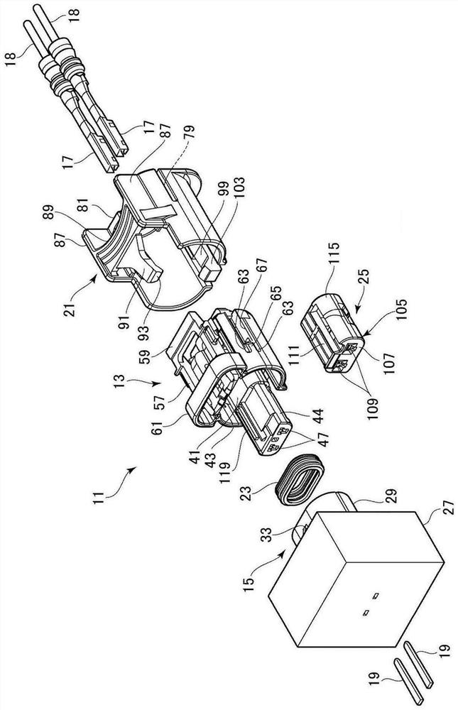
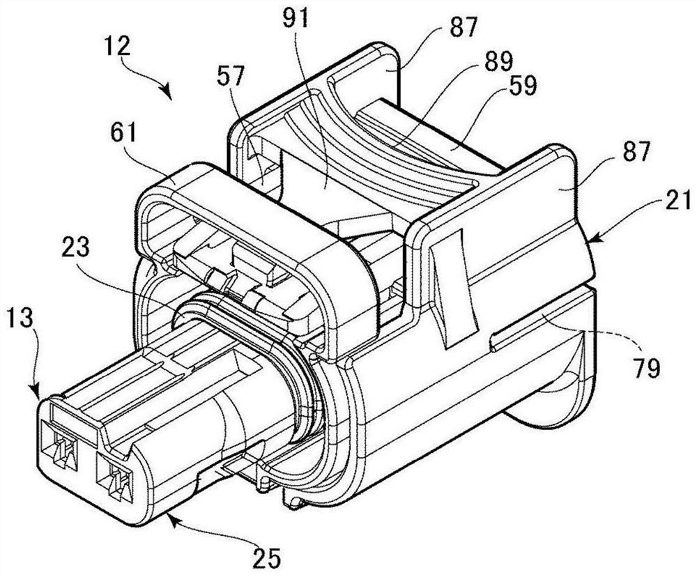
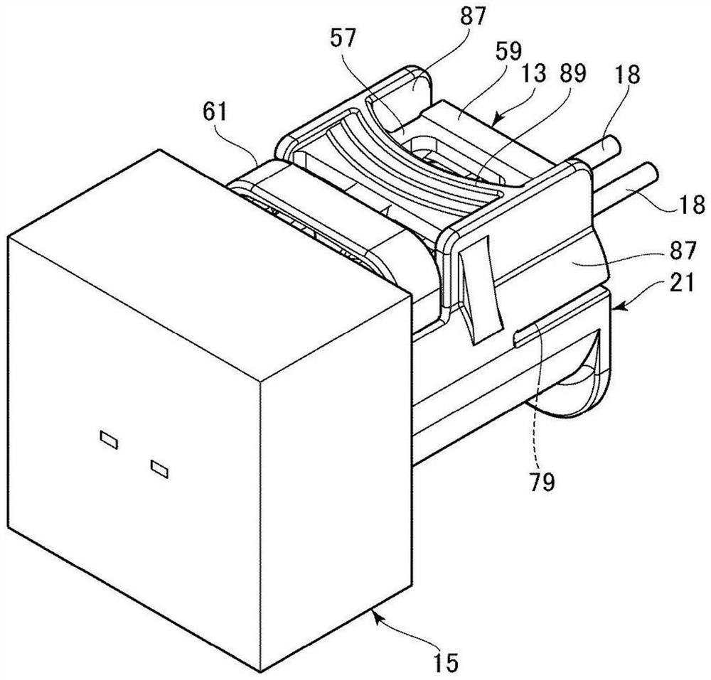
[0103] Embodiments of a connector embodying the present invention will be described below with reference to the drawings. figure 1 is an exploded perspective view of the connector 11 according to the present embodiment. figure 2 is a perspective view of the appearance of the female connector unit (connector unit) 12 in which the CPA 21 , the sealing member 23 and the side holder 25 have been mounted on the female housing 13 . image 3 It is a perspective view of the appearance of the mated state of the connector. Figure 4 to Figure 8 is a longitudinal sectional view showing the movement between the connector before mating and the final locking of the CPA. Incidentally, hereinafter, the direction of mating to the mating connector will be described as forward (forward in the mating direction); the direction of separation from the mating connector will be described as backward (backward in the mating direction); Intersect (approximately orthogonally intersect) on one side ...


PUM


Abstract

The first locking portion (93) of the first component and the second locking portion (55) of the second component have a first locking surface (151) and a second locking surface (161) respectively, and they are positioned at the first locking portion (93). They are opposed to each other in a locked state having been locked to the second locking portion (95). The first inclined surface (155) of the first locking surface (151) and the first abutting portion (153) are arranged in an offset manner in the locking width direction. The second locking surface (161) includes a second inclined surface (167) and a second abutting portion (165). When the first component (21) moves relatively from the locked state to the second component (13) in the opposite direction of the mating direction, the first inclined surface (155) abuts against the second abutting portion (165) and slides on it, And then the first abutting portion (153) abuts and slides on the second inclined surface (167). Therefore, the first locking portion (93) is elastically deformed in a direction opposite to the locking direction by the first inclined surface (155) and the second inclined surface (167) to release the locked state.

Description

technical field [0001] The invention relates to a component locking structure. Background technique [0002] There is a connector formed by fitting a pair of connector housings to each other. When one connector housing for forming a connector is inserted until the one connector housing can be fitted into the mating position of the other connector housing, the terminals accommodated in the respective connector housings are electrically connected to each other, and connected The housings are locked to each other. However, since the mating operation of this type of connector is performed manually, there is fear of terminating the mating operation in a semi-fitted (unlocked) state in which a connector housing has not been inserted into a prescribed mating position without noticing that the rear housing body may be unlocked. [0003] To solve this problem, a connector provided with a fitting position ensuring lock to prevent half-fitting of such connector housings has been pro...

Claims


Application Information

Patent Timeline
Patent Type & Authority Patents(China)
IPC IPC(8): H01R13/639H01R13/64
CPCH01R13/6273H01R13/641H01R13/4362H01R13/6272H01R13/6275
Inventor 大福亮介鹤田哲弘大本高裕新村胜斋藤悠后藤优树远藤高志岩下和之
Owner YAZAKI CORP
Why Eureka
Try Eureka