Gyro and gyro countermeasure method

A technology of gyroscopes and components, which is applied in the fields of gyroscopes, entertainment, toys, etc., can solve the problems of single collision gameplay, large site area requirements, and poor adaptability, and achieve obvious collision effects, small area requirements, and strong adaptability.

Pending Publication Date: 2020-04-28
GUANGZHOU SUNBOY ANIMATION & TOYS CO LTD
View PDF0 Cites 0 Cited by
  • Summary
  • Abstract
  • Description
  • Claims
  • Application Information

AI Technical Summary

Problems solved by technology

[0004] In the existing gyro battle, the collision method is single, and sometimes the collision effect is limited, and the winner cannot be determined immediately after the collision. large, poor adaptability

Method used


Image

  • Gyro and gyro countermeasure method
  • Gyro and gyro countermeasure method
  • Gyro and gyro countermeasure method

Examples


Embodiment 1

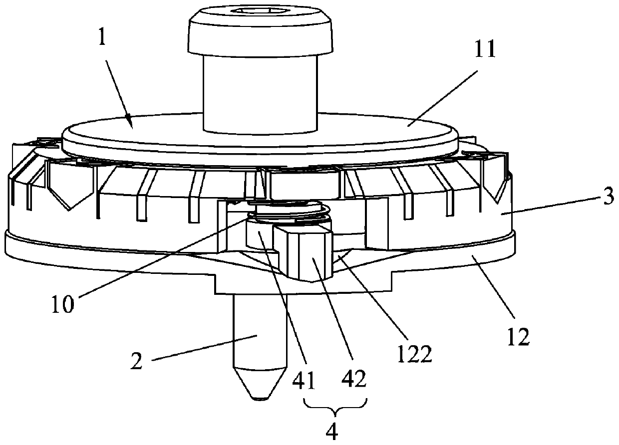
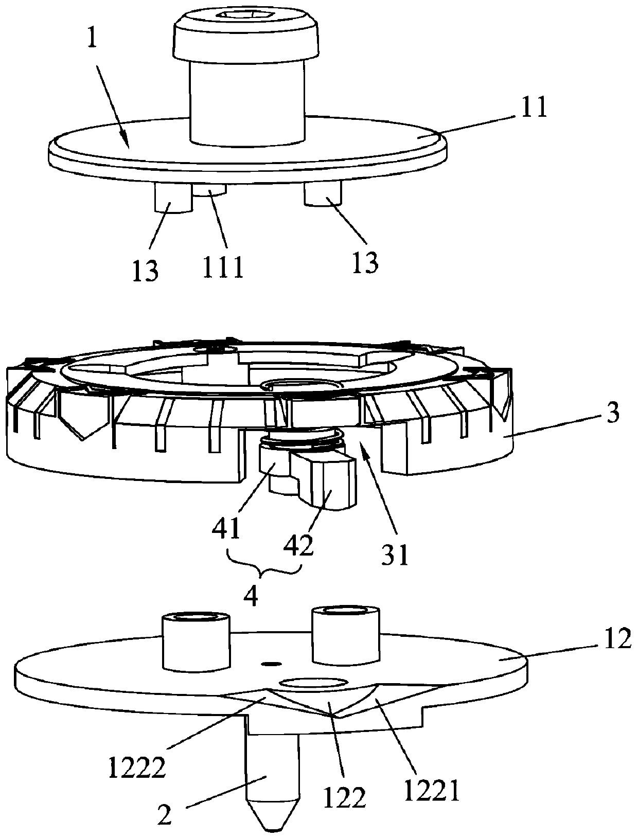
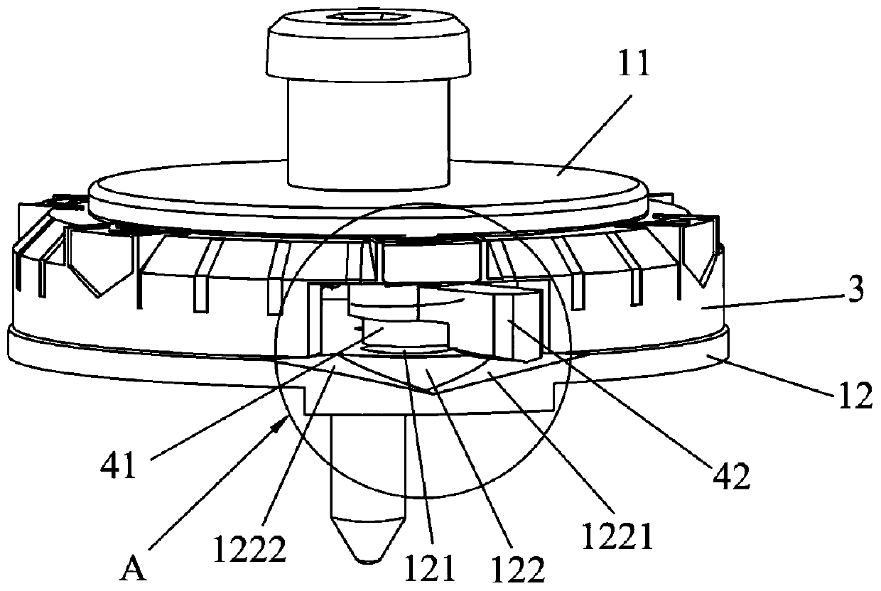
[0056] This embodiment provides a top that can quickly stop rotating after a collision, and quickly determine the winner. Such as figure 1 As shown, the gyroscope includes a body 1 , a central axis gyro tip 2 , a counterweight assembly 3 and a trigger assembly 4 . Wherein, the main body 1 includes an upper cover 11 and a lower cover 12 arranged at intervals up and down, and the upper cover 11 is fixedly connected with the lower cover 12 through a connecting piece 13, where the connecting piece 13 can be the cooperation of a connecting column and a connecting groove, of course, the connection The shape of the part 13 is not limited thereto, for example, it may be a fit between buckle parts, or a fit between magnetic parts. The counterweight assembly 3 is located between the upper cover 11 and the lower cover 12 . The trigger assembly 4 is connected with the counterweight assembly 3, and the trigger assembly 4 can be selectively connected with the lower cover 12 to lock the co...

Embodiment 2

[0063] This embodiment provides a top that can quickly stop rotating after a collision, and quickly determine the winner. see Figure 6 and Figure 7 , the gyroscope includes a body 1 , a central axis gyro tip 2 , a counterweight assembly 3 and a trigger assembly 4 . Wherein, the body 1 includes an upper cover 11 and a lower cover 12 arranged at intervals up and down, and a counterweight assembly 3 and a trigger assembly 4 are arranged between them. The central axis top 2 runs through the upper cover 11 and the lower cover 12 up and down, and coincides with the central axis of the top. A second elastic member 20 is provided between the central axis top 2 and the lower cover 12 . The second elastic member 20 is preferably a spring, and is sheathed on the central axis top 2 . It should be noted that the body 1 also includes a bowl-shaped housing (not shown in the figure), which encloses the lower cover 12 and the central axis top 2, and the lower end of the central axis top ...

Embodiment 3

[0070] This embodiment provides a top that can quickly stop rotating after a collision, and quickly determine the winner. see Figure 8-Figure 10 , the top includes a body 1 , a counterweight assembly 3 and a trigger assembly 4 . Wherein, the body 1 includes an upper cover 11 and a lower cover 12 arranged at intervals up and down, and a limiting cover 14 fixed between them.

[0071] The counterweight assembly 3 is a split structure, including a first counterweight 33 and a second counterweight 34 covered on the limiting cover 14 . The first counterweight 33 is provided with a connecting shaft, and the connecting shaft passes through the limiting cover 14 and is connected with the lower cover 12 . The second counterweight 34 is movably covered on part of the limiting cover 14, and the limiting cover 14 is provided with an avoidance hole 141. The second counterweight 34 is provided with a clamping member 341, and the clamping member 341 is connected by the avoiding hole 141. ...


PUM


Abstract

The invention belongs to the technical field of toys, and particularly discloses a gyro and a gyro countermeasure method. The gyro comprises a body, a counterweight assembly and a trigger assembly. The balance weight assembly is movably arranged on the body. The trigger assembly is connected with the balance weight assembly, the balance weight assembly is unlocked when the trigger assembly on thegyroscope is triggered by collision, the balance weight assembly moves and leaves the locking position, the gravity center of the gyroscope deviates from the rotating center axis of the gyroscope, rotating balance of the gyroscope is destroyed, and the gyroscope stops rotating quickly. When the gyro confronts, the trigger assembly is triggered by collision and unlocks the balance weight assembly,and the balance weight assembly moves and leaves the locking position, so that the gravity center of the whole gyro deviates from the rotating center shaft of the gyro, the rotating balance of the gyro is destroyed, the gyro stops rotating quickly, the collision effect is obvious, winning and losing can be separated quickly, the playing method is novel, and the requirement for the area of a playing place is relatively small.

Description

[0001] This application claims the priority of the following application: Chinese patent application with application number 201911249333.7 filed on December 9, 2019, the entire contents of which are incorporated herein by reference. technical field [0002] The invention relates to the technical field of toys, in particular to a spinning top and a spinning top fighting method. Background technique [0003] As a kind of toy loved by children, the basic gameplay is to launch the top to the contact surface through the transmitter, and then the top will rotate, and two or more tops can collide with each other to compete with each other, so as to improve It is fun to play, and the final victory is determined by the length of the rotation time. [0004] In the existing gyro battle, the collision method is single, and sometimes the collision effect is limited, and the winner cannot be determined immediately after the collision. Larger and less adaptable. Contents of the inventi...

Claims


Application Information

Patent Timeline
Patent Type & Authority Applications(China)
IPC IPC(8): A63H1/00
CPCA63H1/00
Inventor 王晓东
Owner GUANGZHOU SUNBOY ANIMATION & TOYS CO LTD
Why Eureka
Try Eureka