Belt-conveying installation, method for operating the same, and use thereof

A technology of belt conveying and equipment, which is applied in the direction of conveyor, transportation and packaging, etc., and can solve the problems such as the location change of belt conveying equipment

Active Publication Date: 2014-05-14
SIEMENS AG +2
View PDF13 Cites 1 Cited by
  • Summary
  • Abstract
  • Description
  • Claims
  • Application Information

AI Technical Summary

Problems solved by technology

As a result, site position changes of belt conveyors are particularly problematic in mining operations, since the air gap size must always be reliably maintained

Method used


Image

  • Belt-conveying installation, method for operating the same, and use thereof
  • Belt-conveying installation, method for operating the same, and use thereof
  • Belt-conveying installation, method for operating the same, and use thereof

Examples


Embodiment Construction

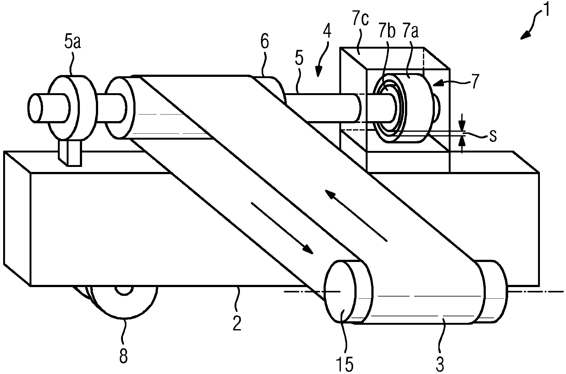
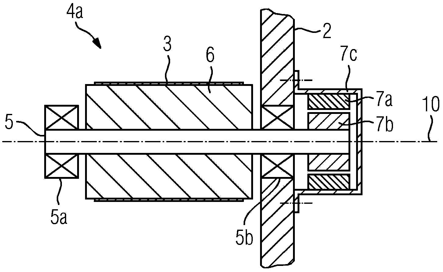
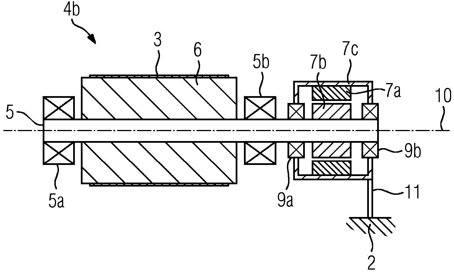
[0047] figure 1 A belt conveyor system 1 for heavy industry, in particular for the raw material industry or the mining industry, is shown schematically and only by way of example in a three-dimensional view. The belt conveyor 1 comprises a carrier structure 2 , a conveyor belt 3 and a drive 4 for driving the conveyor belt 3 . Furthermore, there is at least one guide roller 15 which can likewise be driven and can act as a further drive roller. The drive 4 comprises a drive shaft 5, at least one drive shaft bearing 5a, a drive roller 6 and a separately excited drive motor 7 in the form of an alternating current synchronous motor supplied by a frequency converter, which has a stator 7a and a rotor 7b. The rotor 7 b and the stator 7 a , shown schematically in section, are located in a motor housing 7 c , which is partially transparent here. The drive shaft 5 and the drive motor 7 are connected to one another without gearing, and there is a coaxial arrangement of the rotor 7 b a...


PUM


Abstract

The invention relates to a belt-conveying installation (1) for heavy industry, in particular for the extractive or mining industry, comprising at least one carrying structure (2), a conveying belt (3) and at least one drive apparatus (4) for driving the conveying belt (3), wherein the drive apparatus (4) comprises at least one drive shaft (5), at least one drive-shaft-bearing arrangement (5a), at least one drive roller (6) and at least one independently excited drive motor (7) in the form of a frequency-converter-fed alternating-current synchronous motor with a stator (7a) and a rotor (7b). The drive shaft (5) and the at least one drive motor (7) are connected to one another without any gearing, and the rotor (7b) and drive shaft (5) are arranged coaxially, each drive shaft (5) being guided through at least one rotor (7b). The invention also relates to a method for operating such a belt-conveying installation and to the use thereof.

Description

technical field [0001] The invention relates to a belt conveyor installation for heavy industry, in particular for the raw material industry or mining industry, having at least one carrier structure, a conveyor belt and at least one drive for driving the conveyor belt. The drive device here comprises at least one drive shaft, at least one drive shaft bearing arrangement, at least one drive roller and at least one separately excited drive motor in the form of an alternating current synchronous motor supplied by a frequency converter, the drive motor having a stator and a rotor, wherein , the drive shaft and the at least one drive motor are connected to each other without gearing, and there is a coaxial arrangement of the rotor and the drive shaft. The invention also relates to a method for operating such a belt conveyor and its use. Background technique [0002] Belt conveyors of the aforementioned type are already known. Such a belt conveyor has therefore been installed at...

Claims


Application Information

Patent Timeline
Patent Type & Authority Applications(China)
IPC IPC(8): B65G23/22
CPCB65G23/22B65G15/28
Inventor 克里斯托夫·布雷夫卡霍斯特·迈纳彼得·塞尔诺贝特·贝克尔克里斯蒂安·迪舍尔托尔斯滕·黑尔慕斯沃尔夫·克里格
Owner SIEMENS AG
Why Eureka
Try Eureka