Adjustment Method and Structure of Vertical Stiffness of Primary Suspension Device

A technology of suspension device and adjustment structure, applied in the field of rail vehicles, can solve the problems of difficulty in meeting the actual requirements of vehicle rigidity, difficulty in adapting to the geographical environment, and potential safety hazards, so as to improve the load capacity, dynamic performance and critical speed, and improve the Cornering manoeuvrability and agility, the effect of saving primary suspension space

Active Publication Date: 2021-01-22
ZHUZHOU TIMES RUIWEI ANTI VIBERATION EQUIP LTD
View PDF9 Cites 0 Cited by
  • Summary
  • Abstract
  • Description
  • Claims
  • Application Information

AI Technical Summary

Problems solved by technology

[0003] However, the existing primary suspension devices are all arranged on both sides of the axle box. When the vehicle turns with a small curvature, the rotation angle of the bogie will be restricted by the primary suspension devices on both sides of the axle box, so it is difficult to adapt to multiple The geographical environment of some European countries with mountains and many curves
[0004] If the existing conical springs are directly arranged above the axle box, although small curvature turning can be well realized, but because the space above the axle box is extremely limited, especially the space in the lateral direction is very tight, the primary suspension device realizes Various complex technical requirements are difficult
The stiffness of the conical spring in the vertical, horizontal, and longitudinal directions will be too small, and it is difficult to meet the actual requirements for the stiffness of the vehicle, and there will be safety hazards in the vehicle.

Method used


Image

  • Adjustment Method and Structure of Vertical Stiffness of Primary Suspension Device
  • Adjustment Method and Structure of Vertical Stiffness of Primary Suspension Device
  • Adjustment Method and Structure of Vertical Stiffness of Primary Suspension Device

Examples


Embodiment 1

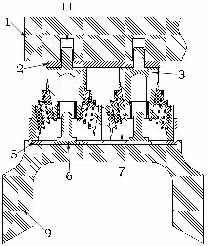
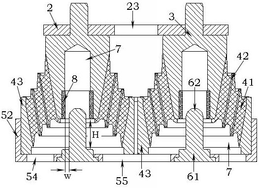
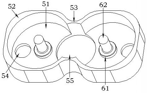
[0028] like figure 1 and figure 2 As shown, a series of suspension devices includes a base 5 , a top plate 2 , a conical spring and a limit stop, wherein the conical spring includes a rubber body 41 , a mandrel 3 and a casing 43 . The lower end of bogie 1 is provided with a stopper hole 11, a single conical spring is a rotating body, and two conical springs are arranged side by side along the longitudinal direction between the base 5 and the top plate 2, and the upper end of the mandrel 3 of the conical spring is separated by a gap. Fitting way is installed in the stopper hole 11. In the middle of the mandrel 3, the rubber body 41 and the jacket 43, there are interconnected cavities 7, and the stop seat 61 at the lower end of the limit stop is engaged in the bottom plate 51 at the lower end of the base 5 in an interference fit manner. The upper end of the limit stop extends into the cavity 7 in the middle of the mandrel 3 . The upper end and the lower end of the axle box s...


PUM


Abstract

The invention provides a method and a structure for adjusting the vertical rigidity of a primary suspension device. The primary suspension device comprises a base, conical springs and limiting stoppers, each conical spring comprises a rubber body and a mandrel, a stopping hole is formed in the lower end of a bogie, the upper end of the mandrel is installed in the stopping hole of the bogie, and cavities are formed in the rubber body and the mandrel; the two conical springs are arranged in the base side by side in the longitudinal direction, the limiting stoppers are arranged in the cavities ofthe conical springs, each limiting stopper comprises a stop base and a stop rod, and the stop rod is integrally formed above the stop base; and an axle box is provided with an axle box seat, the baseis installed in the axle box seat, and when the bogie moves relative to the axle box in the vertical direction and the lower end of the mandrel abuts against the stop seats in the vertical direction,the primary suspension device can generate variable rigidity in the vertical direction. The capacity of a vehicle for passing through a small-curvature-radius curve can be remarkably improved, the primary suspension space is greatly saved, and the weight of the bogie is reduced.

Description

technical field [0001] The invention relates to the field of rail vehicles, in particular to a vertical stiffness adjustment method and structure of a primary suspension device. Background technique [0002] The axlebox built-in bogie is a railway vehicle bogie with the axlebox placed inside the wheel set. This type of bogie effectively reduces the size of the frame space. The minimum curve passing radius of this type of bogie is significantly smaller than that of ordinary bogies. The turning maneuverability and flexibility of this type of bogie are greatly improved. In addition, this type of bogie also satisfies the lightweight design requirements of the bogie to the greatest extent. In order to adapt to the mountainous and curved geographical environment of some European countries, the vehicle often needs to make small turns during driving, which requires the vehicle to have a strong ability to pass through a small radius of curvature. [0003] However, the existing prim...

Claims


Application Information

Patent Timeline
Patent Type & Authority Patents(China)
IPC IPC(8): B61F5/30
CPCB61F5/305
Inventor 兰加标李刚孙海燕谭方冯万盛
Owner ZHUZHOU TIMES RUIWEI ANTI VIBERATION EQUIP LTD
Why Eureka
Try Eureka