A device for cleaning loose ballast around blast holes

A technology for cleaning devices and ballast, which is applied in blasting and other directions, can solve the problems of low work efficiency, easy soreness affecting work efficiency, and affecting blasting accuracy, etc., to achieve high work efficiency

Active Publication Date: 2022-04-05
IN THE TUNNEL BUREAU OF THE SECOND ENG
View PDF0 Cites 0 Cited by
  • Summary
  • Abstract
  • Description
  • Claims
  • Application Information

AI Technical Summary

Problems solved by technology

[0003] At present, people are constantly beating the surrounding soil with tools. It takes a lot of effort. Over time, people's hands are prone to soreness and affect subsequent work efficiency. Pat the loose soil around to avoid the loose soil from falling into the blast hole and affect the blasting accuracy, which will lead to low work efficiency and troublesome operation

Method used


Image

  • A device for cleaning loose ballast around blast holes
  • A device for cleaning loose ballast around blast holes
  • A device for cleaning loose ballast around blast holes

Examples


Embodiment 1

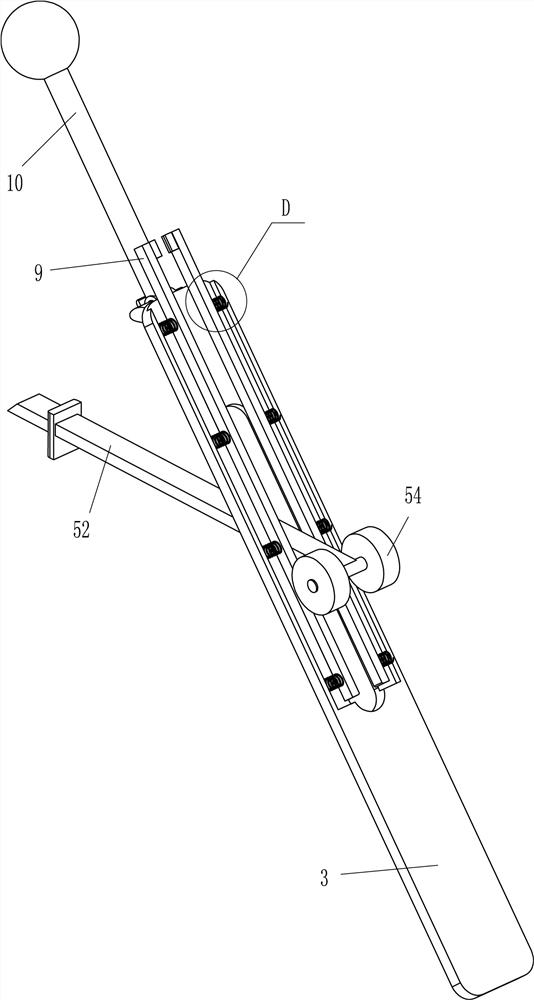
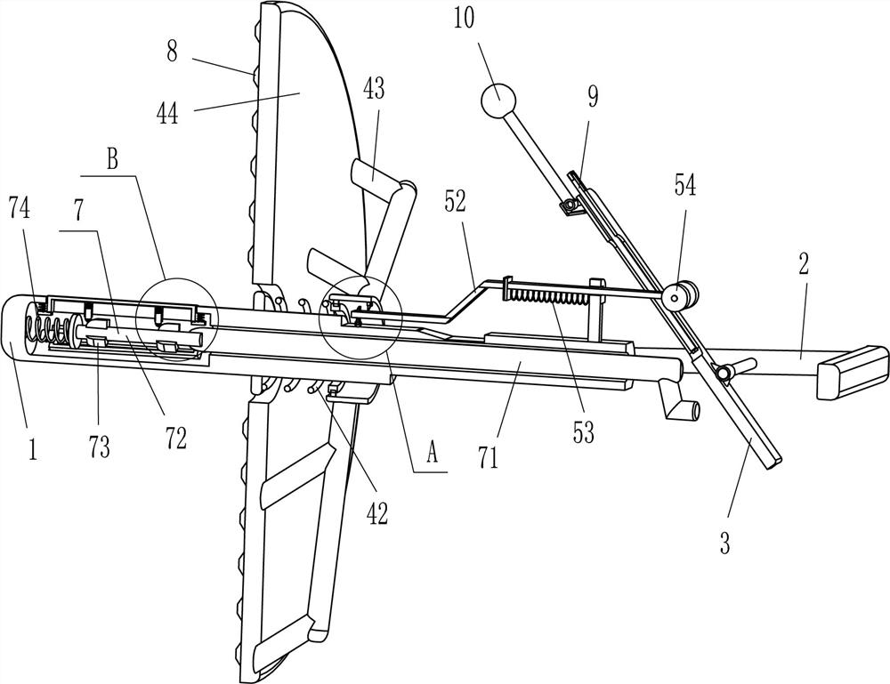
[0024] refer to Figure 1-Figure 5 , a device for cleaning loose ballast around blastholes for blasting, comprising a hollow chute rod 1, a handle 2, a hollow in-line orifice plate 3, a compacting mechanism 4 and a driving mechanism 5, and the right side of the outer side of the hollow chute rod 1 is fixed. A handle 2 is connected, and a hollow in-line orifice plate 3 is hinged between the middle parts of the front and rear sides of the handle 2, and a drive mechanism 5 is provided between the hollow in-line orifice plate 3 and the outer top right side of the hollow chute rod 1, and the hollow chute A compacting mechanism 4 is provided in the middle of the rod 1, and the compacting mechanism 4 is connected with a driving mechanism 5.

[0025] The compacting mechanism 4 includes an annulus 41, the first spring 42, a connecting rod 43 and a beating plate 44. The hollow chute bar 1 middle part slide type is provided with an annulus 41, and the left side of the annulus 41 is conne...

Embodiment 2

[0031] refer to figure 1 , figure 2 and Figure 6 Compared with Embodiment 1, the main difference of this embodiment is that in this embodiment, a fixing mechanism 7 is also included, and the fixing mechanism 7 includes a movable rod 71, a sliding rod 72, an arc block 73, a third spring 74, an arc Plate 75, the 4th spring 76, sleeve 77, circular bar 78 and the 5th spring 79, hollow chute bar 1 sliding type is provided with movable rod 71, movable rod 71 cooperates with hollow word orifice plate 3, movable rod The left end of 71 is fixedly connected with a slide bar 72, the third spring 74 is connected between the left end of the slide bar 72 and the inner left side of the hollow chute bar 1, and the left and right sides of the outside of the slide bar 72 are evenly spaced with arc-shaped blocks 73 , the left part of the hollow chute bar 1 is evenly spaced circumferentially and embedded with arc-shaped plates 75, and a fourth spring 76 is connected between the left and right...

Embodiment 3

[0034] refer to figure 1 , figure 2 , image 3 , Figure 4 , Figure 7 and Figure 8 Compared with Embodiment 1 and Embodiment 2, the main difference of this embodiment is that this embodiment also includes bumps 8, and the left side of the beating plate 44 is fixedly connected with bumps 8 at even intervals.

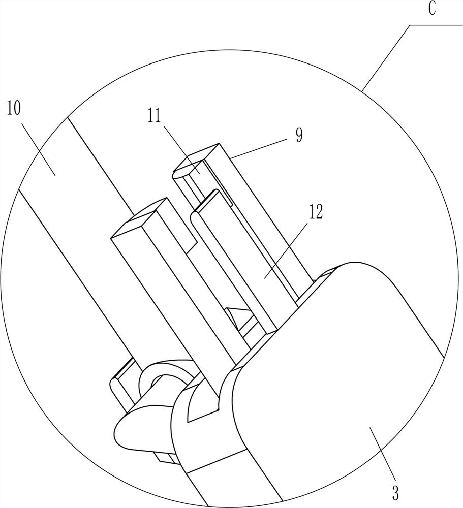
[0035] It also includes a friction clamping plate 9, a swing lever 10, an arc contact block 11, a limit plate 12 and a sixth spring 13, and the friction clamping plate 9 is slidingly provided on the front and rear sides of the hollow in-line hole plate 3. , the inner surface of the friction clamping plate 9 is in contact with the side surface of the special-shaped plate 52, and the sixth spring 13 is evenly spaced between the outer surface of the friction clamping plate 9 and the inner surface of the hollow orifice plate 3, and the friction clamping plates on the front and rear sides The upper part of the inner surface of 9 is fixedly connected with an arc-shaped ...


PUM


Abstract

The invention relates to a cleaning device, in particular to a device for cleaning loose stones around blast holes. The technical problem is how to design a kind of can be convenient for people to carry out compacting to the soil around the blast hole, and the loose ballast cleaning device around the blast hole for blasting with high work efficiency. A device for cleaning loose ballast around blastholes for blasting, comprising a hollow chute rod, a handle is fixedly connected to the outer end of the hollow chute rod, and the hollow in-line orifice plate is connected between the inner sides of the handle; The mechanism is installed on the outside of the hollow chute rod, and it is used to compact the soil around the blast hole. By inserting the hollow chute rod into the blast hole, the beating plate is in contact with the soil, and the hollow orifice plate is pulled to continuously swing, so that the beating plate can continuously move left and right to beat the soil around the blast hole without using tools by hand. It is more convenient to slap the soil vigorously, and the work efficiency is also high.

Description

technical field [0001] The invention relates to a cleaning device, in particular to a device for cleaning loose stones around blast holes. Background technique [0002] Blasting is a technology that uses the compression, loosening, destruction, throwing and killing effects of explosives in air, water, earth and rock media or objects to achieve the intended purpose. When the explosive package or charge explodes in the earth-rock medium or structure, the earth-rock medium or structure will be compressed, deformed, destroyed, loosened and thrown. It is mainly used in earthwork engineering, and the demolition of metal buildings and structures. The scope of the research includes: the properties and methods of use of explosives and firearms, the explosive effect of charges (charges) in various media, the contact blasting and non-contact blasting of charges on targets, and the organization and implementation of various blasting operations , you need to open a blasthole at the blas...

Claims


Application Information

Patent Timeline
Patent Type & Authority Patents(China)
IPC IPC(8): F42D1/00
CPCF42D1/00
Inventor 王伟东上官洲境郭伟平王菊琴常佳昊李继成许瑞李鹏飞吕志锟
Owner IN THE TUNNEL BUREAU OF THE SECOND ENG
Why Eureka
Try Eureka