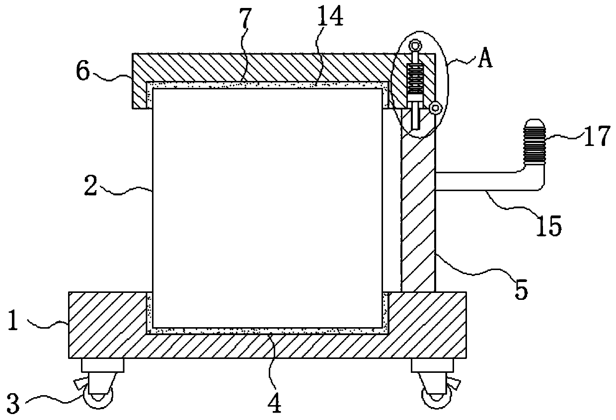
Transformer moving equipment for railway

A technology for mobile equipment and transformers, which is applied in the direction of transformer handling devices, transformer/inductor parts, circuits, etc. It can solve problems such as transformers are prone to offset, and achieve the effect of ensuring stability and convenient limit fixation

Inactive Publication Date: 2020-04-28
TIANJIN YUANHE HUATIE ELECTRICAL EQUIP
View PDF0 Cites 1 Cited by
  • Summary
  • Abstract
  • Description
  • Claims
  • Application Information

AI Technical Summary

Problems solved by technology

[0004] The purpose of the present invention is to solve the problem that transformers in the prior art usually use ropes to limit and fix the transformer during transportation, which leads to the problem that the transformer is prone to shift during transportation, and proposes a transformer mobile device for railways

Method used


Image

  • Transformer moving equipment for railway
  • Transformer moving equipment for railway

Examples


Embodiment Construction

[0019] The following will clearly and completely describe the technical solutions in the embodiments of the present invention with reference to the accompanying drawings in the embodiments of the present invention. Obviously, the described embodiments are only some, not all, embodiments of the present invention.

[0020] In describing the present invention, it should be understood that the terms "upper", "lower", "front", "rear", "left", "right", "top", "bottom", "inner", " The orientation or positional relationship indicated by "outside", etc. is based on the orientation or positional relationship shown in the drawings, and is only for the convenience of describing the present invention and simplifying the description, rather than indicating or implying that the referred device or element must have a specific orientation, so as to Specific orientation configurations and operations, therefore, are not to be construed as limitations on the invention.

[0021] refer to Figure ...


PUM


Abstract

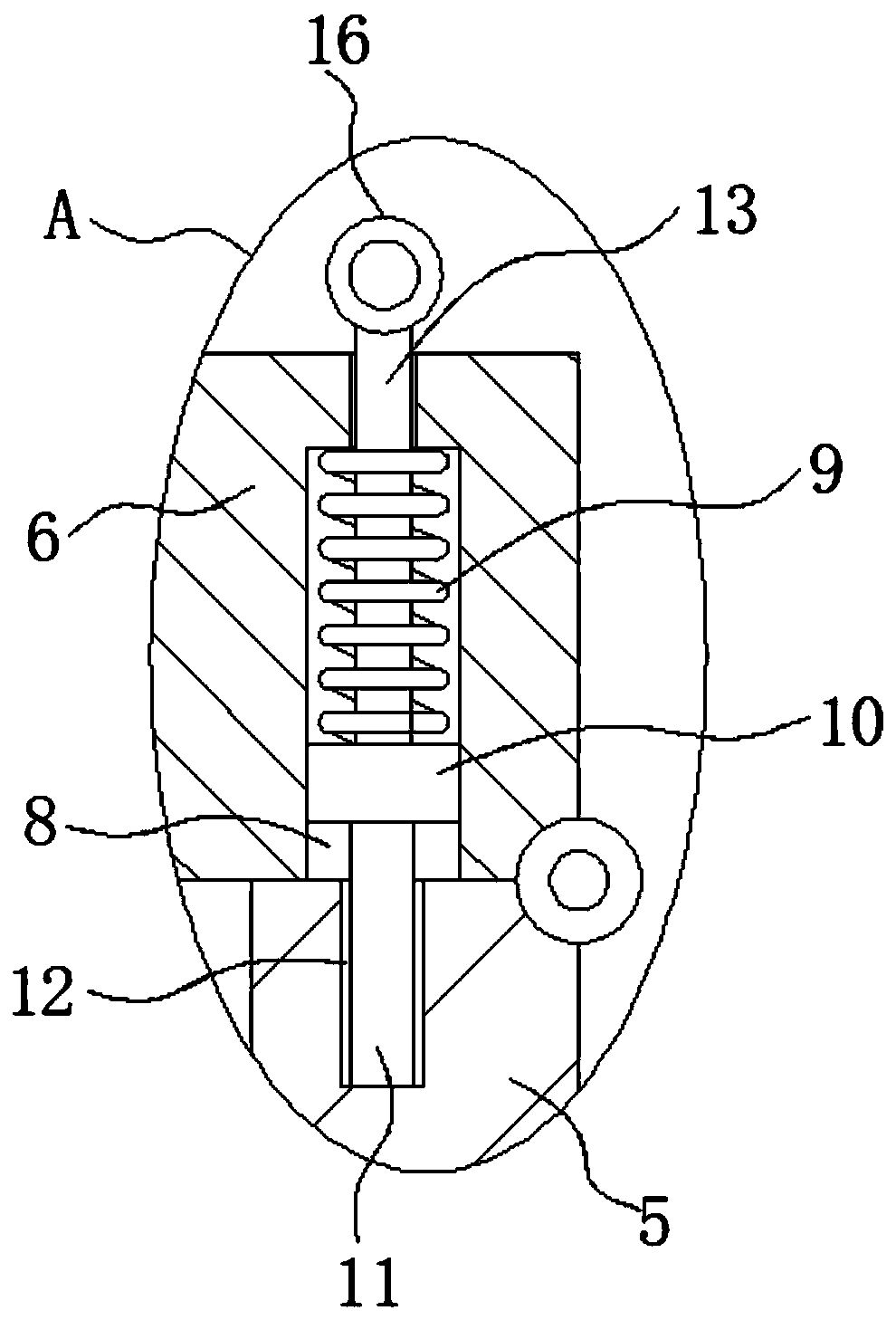
The invention relates to the technical field of transformer transportation, and discloses transformer moving equipment for the railway. The transformer moving equipment comprises a bearing bottom plate and a transformer body, wherein universal wheels are fixedly mounted at the four corners of the bottom of the bearing bottom plate respectively, a groove matched with the transformer body is formedin the upper surface of the bearing bottom plate; the bottom of the transformer body abuts against the bottom of the groove, a side plate is fixedly connected to the upper surface, which is close to one end, of the bearing bottom plate, a top plate is rotatably connected to the upper surface of the side plate through a rotating pin, a locking mechanism is mounted between the top plate and the sideplate, a buckling groove matched with the transformer body is formed in the lower surface of the top plate, and the top of the transformer body abuts against the bottom of the buckling groove; the locking mechanism comprises a sliding block groove formed in the lower surface of the top plate, the sliding block groove is close to the rotating pin, and a spring is fixedly connected to the bottom ofthe sliding block groove. The transformer can be conveniently and quickly limited and fixed, and the moving stability of the transformer is effectively guaranteed.

Description

technical field [0001] The invention relates to the technical field of transformer transportation, in particular to a transformer moving equipment for railways. Background technique [0002] The transformer is a device that uses the principle of electromagnetic induction to change the AC voltage. The main components are the primary coil, the secondary coil and the iron core (magnetic core). The main functions are: voltage conversion, current conversion, impedance conversion, isolation, voltage stabilization (magnetic saturation transformer), etc. According to the purpose, it can be divided into: power transformers and special transformers. [0003] When the existing transformer needs to be transported, the transformer is usually placed on the movable car body plate by a crane, and then fixed by a rope to limit the position. Since there is no good fixing method, the transformer is prone to shift during transportation. There is a certain risk, and the way of fixing the rope ...

Claims


Application Information

Patent Timeline
Patent Type & Authority Applications(China)
IPC IPC(8): H01F27/00
CPCH01F27/002
Inventor 杨洪智
Owner TIANJIN YUANHE HUATIE ELECTRICAL EQUIP
Why Eureka
Try Eureka