A high-pass optical ion trap device

A photoion and ion trap technology, applied in particle separation tubes, dynamic spectrometers, trajectory-stabilized spectrometers, etc., can solve the problems of complex production process, poor light transmission, harsh application environment, etc., and achieve increased ion life and ion collision. The effect of reducing the probability and improving the light transmission

Active Publication Date: 2021-10-01
合肥幺正量子科技有限公司
View PDF7 Cites 0 Cited by
  • Summary
  • Abstract
  • Description
  • Claims
  • Application Information

AI Technical Summary

Problems solved by technology

[0006] The invention provides a high-pass optical ion trap device, which is at least used to solve the problems of complex manufacturing process, harsh application environment and poor light transmission

Method used


Image

  • A high-pass optical ion trap device
  • A high-pass optical ion trap device
  • A high-pass optical ion trap device

Examples


Embodiment Construction

[0026] In order to make the object, technical solution and advantages of the present invention clearer, the present invention will be described in further detail below in conjunction with specific embodiments and with reference to the accompanying drawings.

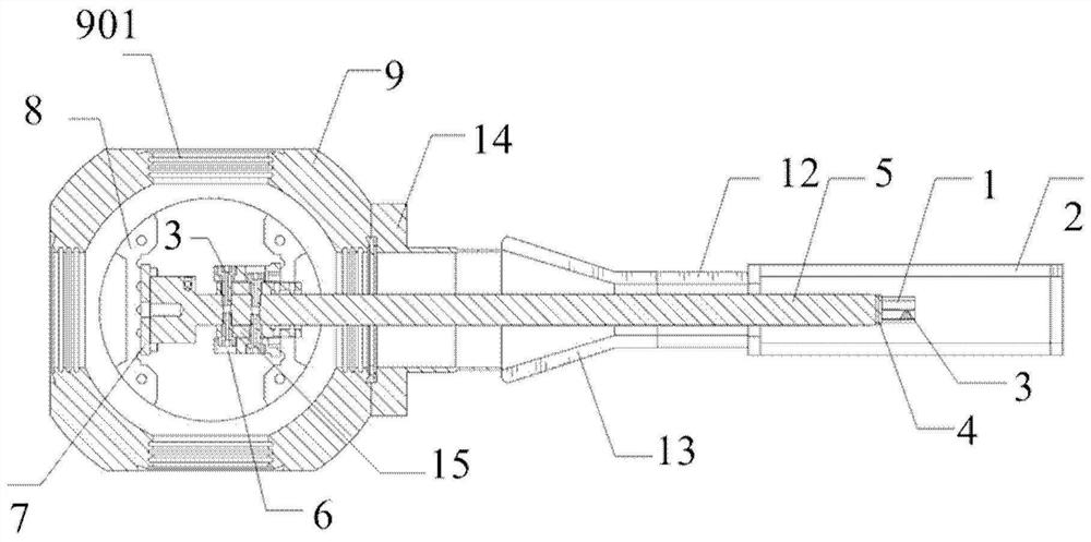
[0027] refer to figure 1 , figure 1 It schematically shows the structural diagram of the high-pass optical ion trap device of the present invention. The high-pass optical ion trap device comprises: an ion trap blade set 1 and a glass chamber 2, and the ion trap blade set 1 is arranged at the intersection of the glass chamber 2 diagonals.

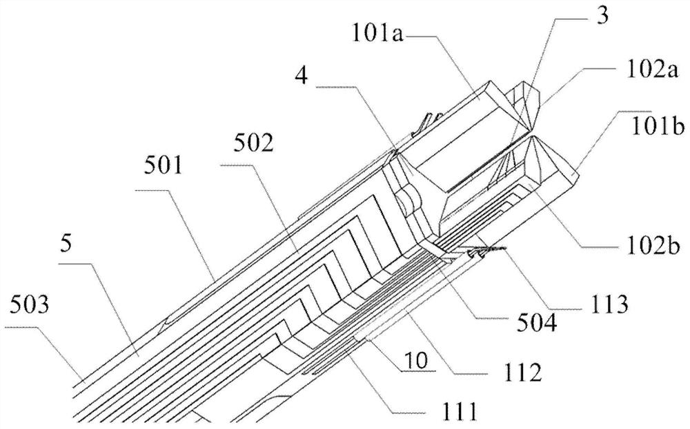
[0028] The ion trap blade set 1 includes a pair of radio frequency electrodes 101 and a pair of direct current electrodes 102. A pair of radio frequency electrodes 101 and a pair of direct current electrodes 102 form four light angles, and the four vertices of the four light angles are surrounded by The plane has a central axis, and the vertical distances from the four vertices to the...


PUM


Abstract

The invention provides a high-pass optical ion trap device, comprising an ion trap blade set (1) and a glass chamber (2), and the ion trap blade set (1) is arranged at the intersection of diagonal lines of the glass chamber (2); The ion trap blade set (1) includes a pair of radio frequency electrodes (101) and a pair of direct current electrodes (102). The pair of radio frequency electrodes (101) and the pair of direct current electrodes (102) form four angles of light transmission, and the four transmission angles The plane surrounded by the four vertices of the light angle has a central axis, the vertical distances of the four vertices from the central axis are equal, and the area obtained by extending the plane along the direction of the central axis is the central prison area (3); the four light-passing angles One-to-one corresponds to the four transparent glass surfaces of the glass chamber (2); the distance between the central axis and the outer surfaces of the four transparent glass surfaces can be adjusted.

Description

technical field [0001] The invention relates to the fields of quantum information, quantum chemistry, optical frequency standard and quantum optics, in particular to an ion trap device with high optical transparency. Background technique [0002] An ion trap is a device that uses magnetic or radio frequency electric fields to confine single or multiple ions. In the US patent US 2939952 invented by Wolfgang Paul in 1953, Paul trap was proposed, which uses radio frequency electric field and electrostatic field to realize the confinement of charged particles. The Paul trap uses a pair of oppositely placed hyperboloid metal electrodes as radio frequency electrodes, which is difficult to manufacture, difficult to assemble, and has poor light transmission. Later, a batch of structurally improved Paul wells appeared, such as linear quadrupole wells, linear blade wells, micro-nano-processed chip wells, and surface wells. [0003] However, due to the small number of DC electrodes i...

Claims


Application Information

Patent Timeline
Patent Type & Authority Patents(China)
IPC IPC(8): H01J49/02H01J49/42
CPCH01J49/02H01J49/4205
Inventor 贺冉崔金明李睿睿钱忠华黄运锋李传锋
Owner 合肥幺正量子科技有限公司
Why Eureka
Try Eureka