
a display panel

A display panel and display area technology, applied in semiconductor devices, electrical components, photovoltaic power generation, etc., can solve the problems of widening the non-display area width of the device boundary and reducing the screen ratio, so as to improve the bending reliability and shorten the boundary Width, to achieve the effect of a narrow border

Active Publication Date: 2022-07-12
WUHAN CHINA STAR OPTOELECTRONICS SEMICON DISPLAY TECH CO LTD
View PDF5 Cites 0 Cited by
  • Summary
  • Abstract
  • Description
  • Claims
  • Application Information

AI Technical Summary

Problems solved by technology

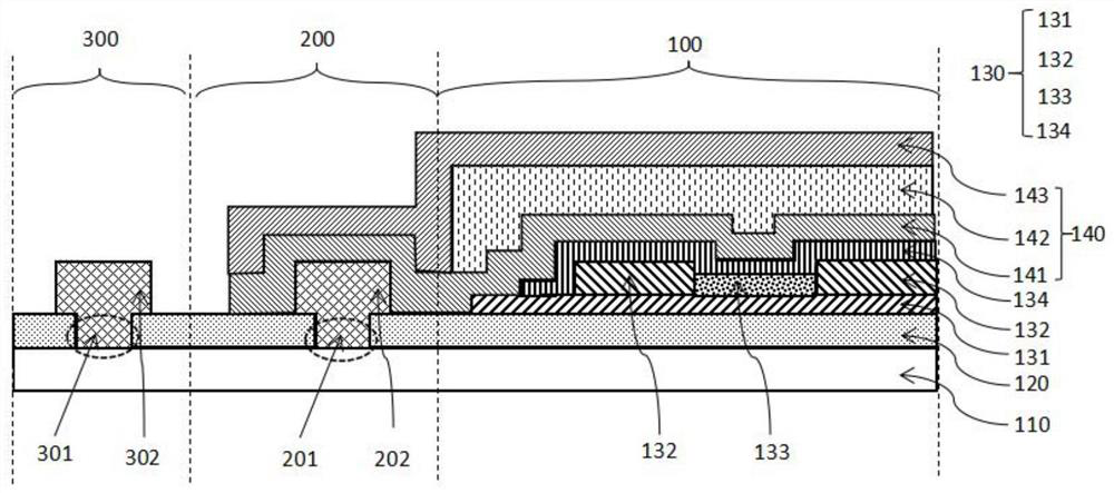
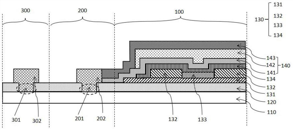
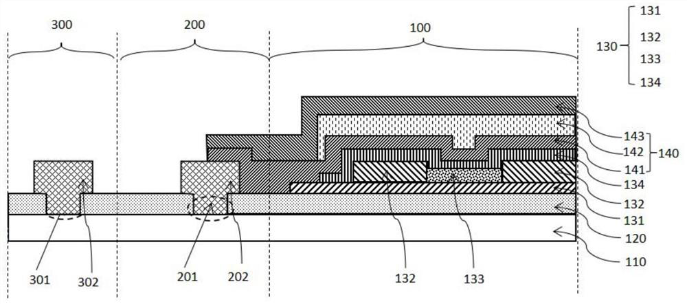
[0005] The purpose of the present invention is to provide a display panel to solve the technical problem in the prior art that adding a crack prevention structure at the boundary of the OLED device will further widen the width of the non-display area of ​​the device boundary and reduce the screen ratio

Method used


Image

  • a display panel
  • a display panel
  • a display panel

Examples


Embodiment Construction

[0028] The following descriptions of the various embodiments refer to the accompanying drawings to illustrate specific embodiments in which the present application may be practiced. Directional terms mentioned in this application, such as [upper], [lower], [front], [rear], [left], [right], [inner], [outer], [side], etc., are only for reference Additional schema orientation. Therefore, the directional terms used are used to describe and understand the present application, rather than to limit the present application. In the figures, structurally similar elements are denoted by the same reference numerals.

[0029] The specific embodiments of the display panel provided by the present invention will be described in detail below with reference to the accompanying drawings.

[0030] figure 1 It is a schematic structural diagram of a display panel according to an embodiment of the present invention. see figure 1 , In this embodiment, a display panel is provided, which has a dis...


PUM

PropertyMeasurementUnit
thicknessaaaaaaaaaa
thicknessaaaaaaaaaa
thicknessaaaaaaaaaa

Abstract

The invention provides a display panel, which has a display area, a barrier wall area surrounding the display area, and an edge area surrounding the barrier wall area; the display panel includes a substrate; an orthographic projection on the substrate an inorganic layer located in the display area, the retaining wall area and the edge area; a light-emitting functional layer disposed on the inorganic layer; and an encapsulation layer disposed on the light-emitting functional layer and covering the light-emitting functional layer , and the orthographic projection of the encapsulation layer on the substrate is located in the display area and the retaining wall area; the inorganic layer located in the edge area is provided with at least one first slot, and the first opening A first filler is arranged in the groove to form a crack prevention structure, which can restrain the cracks generated at the boundary from expanding in the bending process, and help to achieve the effect of narrow frame.

Description

technical field [0001] The present invention relates to the field of display, in particular to a display panel. Background technique [0002] With the development of science and technology and the improvement of human's requirements for the quality of life, various display electronic devices have entered the field of vision of human beings, and users' requirements for electronic devices are constantly being refreshed. Taking liquid crystal display panels as an example, flexible OLED display panels are Its high color gamut and high applicability are widely used. [0003] At present, in order to ensure the bending reliability of foldable flexible OLED devices, crack prevention structures are usually prepared in the bending boundary area of ​​the OLED device to prevent the cracks generated during the bending process from extending inward, reducing the bending of the OLED device. reliability. In the prior art, the design of a crack prevention structure is introduced at the per...

Claims


Application Information

Patent Timeline
Patent Type & Authority Patents(China)
IPC IPC(8): H01L27/32H01L51/52H01L51/56
CPCH10K59/122H10K50/8426H10K71/00Y02E10/549
Inventor 汪衎
Owner WUHAN CHINA STAR OPTOELECTRONICS SEMICON DISPLAY TECH CO LTD
Learn More