Hydraulic control type bus lifting ring

A bus and lifting ring technology, applied in vehicle parts, special positions of vehicles, transportation and packaging, etc., can solve problems such as danger, insufficient use of seats, passengers falling, etc., to prevent slipping hands, ensure balance, reduce effect of temperature

Inactive Publication Date: 2020-05-01
吴小花
View PDF3 Cites 6 Cited by
  • Summary
  • Abstract
  • Description
  • Claims
  • Application Information

AI Technical Summary

Problems solved by technology

[0002] Due to the large number of people taking the bus, the seats on the bus are often not enough to use, and the passengers usually stand on the bus. In order to make the passengers stand more stably, some suspension rings are arranged on the bus. People can hold the lifting rings to ensure their own balance. These rings can usually shake for the convenience of passengers to adjust their positions. However, during the driving process of the car, there will usually be some emergency braking. At this time, the passengers and the rings will move forward due to inertia, which will easily cause the passengers to fall and cause danger. Therefore, it is necessary to design a bus ring to solve the above problems

Method used


Image

  • Hydraulic control type bus lifting ring
  • Hydraulic control type bus lifting ring

Examples


Embodiment 1

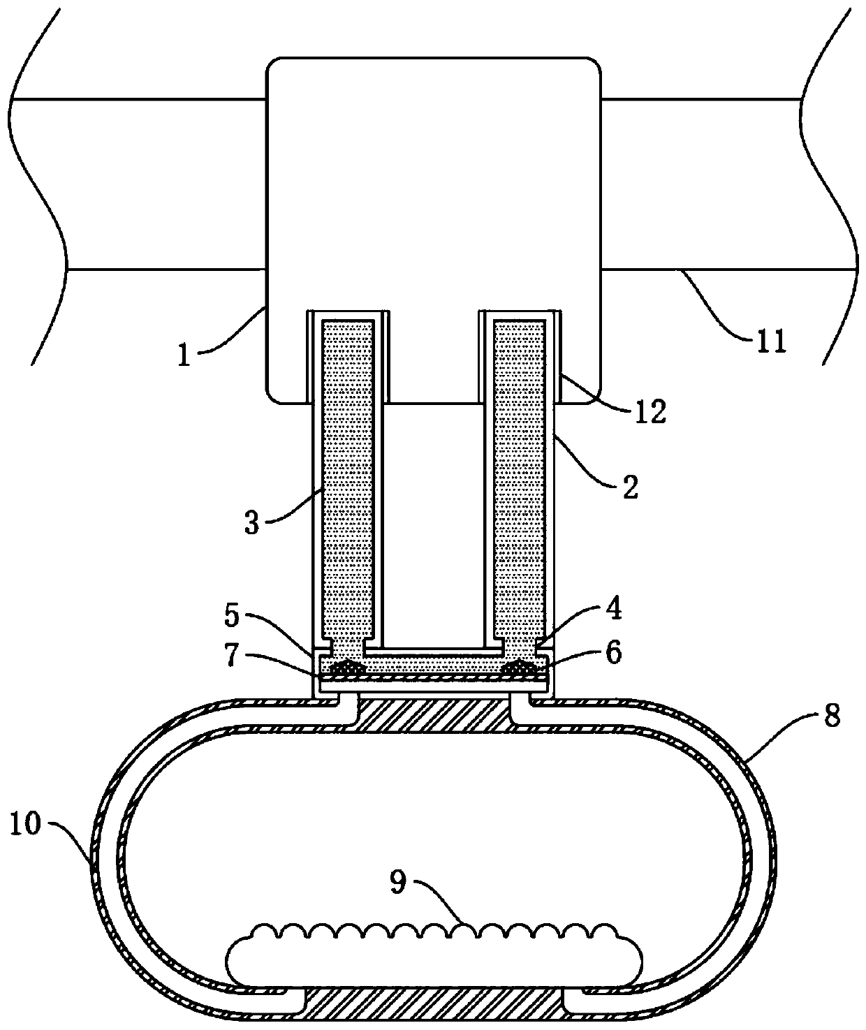
[0017] refer to figure 1 , a hydraulically controlled bus suspension ring, comprising a railing 11, the side wall of the railing 11 is fixedly sleeved with a fixed block 1, the lower end of the fixed block 1 is provided with a pull ring 8, and the lower wall of the fixed block 1 is provided with two control grooves 12, two The inner walls of each control groove 12 are fixedly connected with a steel wire hose 2, the steel wire hose 2 can be bent, and when bending, the size of the space inside the pipe will change, and the lower walls of the two steel wire hoses 2 are fixedly connected with a connection box 5 , the lower walls of the two steel wire hoses 2 are connected with the connection box 5 through the communication port 4, the lower wall of the connection box 5 is fixedly connected with the pull ring 8, the two steel wire hoses 2 are filled with the filling liquid 3, and the filling liquid 3 The total volume is slightly larger than the sum of the spaces inside the two stee...

Embodiment 2

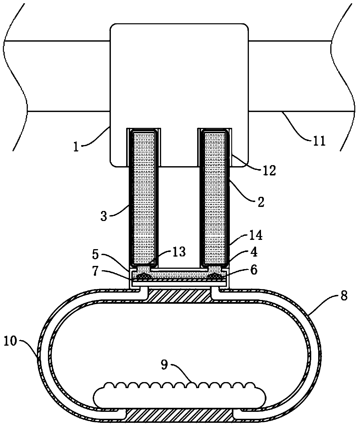
[0023] refer to figure 2 , a hydraulically controlled bus suspension ring, the inner walls of the two communication ports 4 are fixedly connected with piezoelectric ceramics 13, and the diameter of the piezoelectric ceramics 13 is smaller than the diameter of the communication port 4, ensuring that the piezoelectric ceramics 13 will not block the communication ports 4. The piezoelectric ceramic 13 can generate current when it is squeezed by an external force. Further, in order to prevent the filling liquid 3 from interfering with the conduction of the piezoelectric ceramic 13, a protective film can be provided on the side wall of the piezoelectric ceramic 13. Two steel wires The inside of the side wall of the hose 2 is equipped with a lead frame 14, and the two piezoelectric ceramics 13 are electrically connected to the two lead frames 14 respectively. The filling liquid 3 is a magnetorheological fluid, which is a kind of Suspensions, when subjected to magnetic forces, gradua...


PUM


Abstract

The invention discloses a hydraulic control type bus lifting ring, which comprises a handrail, wherein the side wall of the handrail is fixedly sleeved with a fixed block, a pull ring is arranged at the lower end of the fixed block, two control grooves are formed in the lower wall of the fixed block, the inner walls of the two control grooves are fixedly connected with steel wire hoses, the lowerwalls of the two steel wire hoses are jointly and fixedly connected with a connecting box, the lower walls of the two steel wire hoses communicate with the connecting box through communicating openings, the lower wall of the connecting box is fixedly connected with the pull ring, the two steel wire hoses are filled with a filling liquid, the inner wall of the connecting box is connected with a control panel in a sealed and sliding mode, the side wall of the control panel is fixedly connected with two control plugs matched with the communicating openings, and the side wall of the inner ring, close to the lower end, of the pull ring is fixedly connected with an air bag. According to the invention, passengers can be effectively helped to well guarantee the balance of themselves, and the situation that the pull ring slips off the hand due to sweating of heat generated by friction when people hold the pull ring for a long time is prevented.

Description

technical field [0001] The invention relates to the technical field of public equipment, in particular to a liquid-controlled bus suspension ring. Background technique [0002] Due to the large number of people on the bus, the seats on the bus are often not enough, and the passengers usually stand on the bus. In order to make the passengers stand more stably, some suspension rings are arranged on the bus. People can hold the lifting rings to ensure their own balance. These rings can usually be shaken for the convenience of passengers to adjust their positions. At the same time, the passenger and the suspension ring will move forward due to inertia, which will easily cause the passenger to fall down and cause danger. Therefore, a kind of bus suspension ring needs to be designed to solve the above problems. Contents of the invention [0003] The purpose of the present invention is to solve the shortcomings in the prior art, and propose a hydraulically controlled bus suspens...

Claims


Application Information

Patent Timeline
Patent Type & Authority Applications(China)
IPC IPC(8): B60N3/02
CPCB60N3/026
Inventor 吴小花张洋洋
Owner 吴小花
Why Eureka
Try Eureka