Rotating block type derailer device

A derailer and rotating block technology, which is used in transportation and packaging, equipment fixed to the track, railway car body parts, etc., can solve the problem that the height of the stop block cannot be too high, the train cannot be safely derailed, and the derailment head is easy to retreat, etc. problems, to achieve the effect of flexible adjustment in place, ingenious design ideas, and high safety and reliability coefficient

Inactive Publication Date: 2020-05-01
HUANGSHI BANGKE TECH CO LTD
View PDF1 Cites 0 Cited by
  • Summary
  • Abstract
  • Description
  • Claims
  • Application Information

AI Technical Summary

Problems solved by technology

[0002] The derailer is an indispensable personnel security inspection equipment on the railway train inspection field. The derailment head of the traditional derailer is flat. Due to the horizontal thrust of the edge, when the derailment head moves backward under the horizontal thrust, the stop block at the lower end of the derailment head will lift the derailment head up and down, and the bearing will be broken, and the shaft will be damaged. Because the horizontal thrust is too large and the forces are different, the derailment head will move backward. The distances are also different, so some derailers can take off the train wheels during use, and some can’t, which poses a great safety hazard. There is also a kind of derailer that has a downward protrusion on the outer end of the upper end of the derailment head and the outer end of the bottom surface of the rail. (See Patent No. 201020297332.8). This type of derailer is better than the traditional old derailer, but it also has the following defects: First, the derailment head is derailed up and down by sliding, and the upper end of the derailment head The height of the stop block should not be too high, and the stability is not enough; the second is that under the action of horizontal force, the derailment head is easy to retreat. Due to the difference in the distance of retreat, the retreat is too much, so that the train sometimes cannot derail safely, causing accidents

Method used


Image

  • Rotating block type derailer device
  • Rotating block type derailer device
  • Rotating block type derailer device

Examples


Embodiment Construction

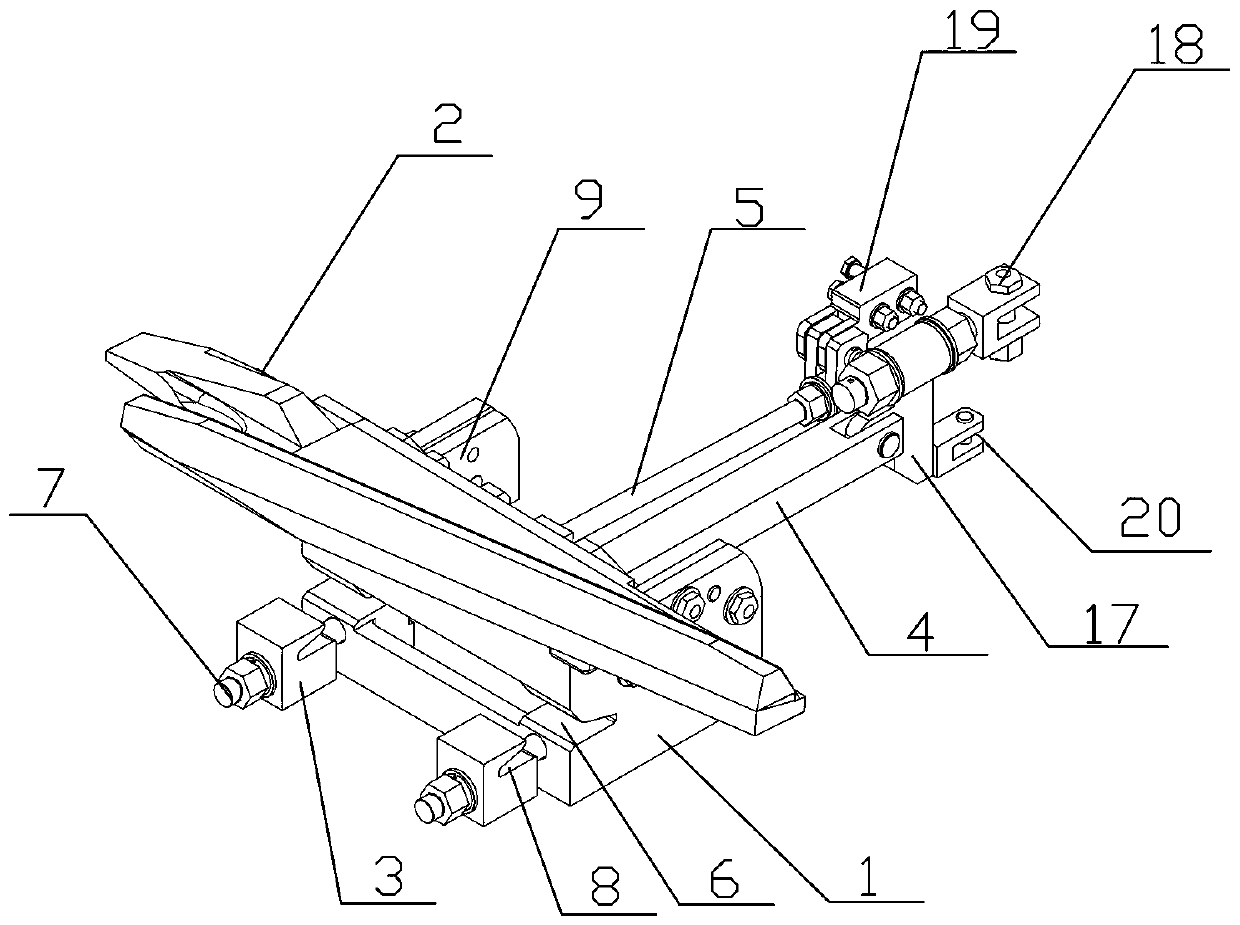
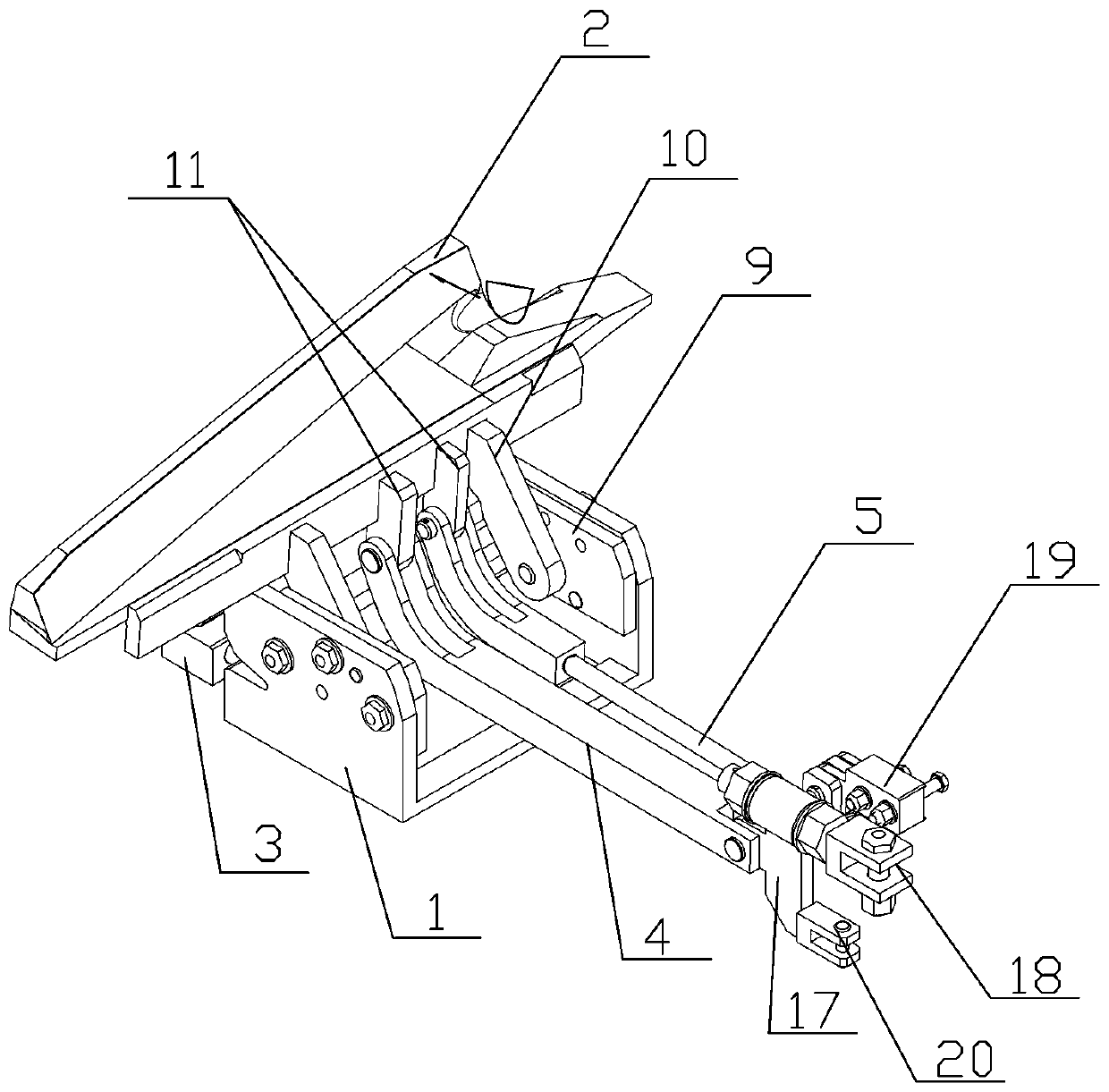
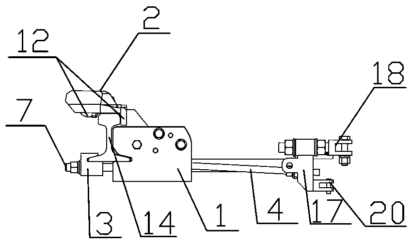
[0015] see Figure 1-5 , the present embodiment of the present invention rotating block type derailer device, including a base 1, a derailment head 2, a rail block 3, a main push-pull rod 4, a driven rod 5, a main push-pull rod adapter 17, a driven rod adapter 19 and adjustment Rod 18, the front end of the base is provided with a rail slot A6, at least one bolt rod 7 is provided on the base below the rail slot A, the bolt rod is equipped with a rail block, and the rail block is provided with a rail Card slot B8, a transition support plate 9 is respectively provided on both sides of the base, and a first-level ear plate 10 is arranged on each transition support plate, one end of the first-level ear plate is hinged with the transition support plate, and the other end of the first-level ear plate is hinged. One end is fixedly connected to the derailment head, and two secondary ear plates 11 are arranged side by side between the two primary ear plates. One end of the two secondary...


PUM


Abstract

The invention discloses a rotating block type derailer device. The device comprises a base, a derailer head, a rail clamping block, a main push-pull rod, a driven rod, a main push-pull rod adapter, adriven rod adapter and an adjusting rod, wherein a rail clamping groove A is formed in the front end of the base; at least one bolt rod is arranged on the base below the rail clamping groove A; the rail clamping block is arranged on the bolt rod; the rail clamping block is provided with a rail clamping groove B; the two sides of the base are each provided with a transition supporting plate; a first-stage lug plate is arranged on each transition supporting plate; one end of the first-stage lug plate is hinged with the transition supporting plate; the other end of the first-stage lug plate is connected with the derailer head; two second-stage lug plates are arranged between the two first-stage lug plates side by side, one ends of the two second-stage lug plates are connected with the derailer head, the other ends of the two second-stage lug plates are correspondingly hinged to the main push-pull rod and one end of the driven rod, the other end of the main push-pull rod is hinged to the main push-pull rod adapter, and the upper end of the main push-pull rod adapter is connected with the adjusting rod; and the driven rod is connected with the driven rod adapter. The device is ingenious, simple and reasonable in thought and high in up-and-down separation safety and reliability coefficient.

Description

technical field [0001] The invention relates to the field of safety protection for railway line vehicle maintenance, in particular to a rotating block type derailer device. Background technique [0002] The derailer is an indispensable personnel security inspection equipment on the railway train inspection field. The derailment head of the traditional derailer is flat. Due to the horizontal thrust of the edge, when the derailment head moves backward under the horizontal thrust, the stop block at the lower end of the derailment head will lift the derailment head up and down, and the bearing will be broken, and the shaft will be damaged. Because the horizontal thrust is too large and the force is different, the derailment head will move backward. The distances are also different, so some derailers can take off the train wheels during use, and some cannot, which poses a great safety hazard. There is also a downward protrusion on the outer end of the upper end of the derailment ...

Claims


Application Information

Patent Timeline
IPC IPC(8): B61K5/06B61K13/00
CPCB61K5/06B61K13/00
Inventor 柯智强焦海余金彪曾勇程培强
Owner HUANGSHI BANGKE TECH CO LTD
Why Eureka
Try Eureka