Parallel type lower water valve structure of humidifier and combined use mode thereof

A parallel, humidifier technology, applied in heating methods, air humidification systems, applications, etc., can solve problems such as hidden safety hazards, humidifier water leakage, internal circuit short circuit, etc., to enhance safety and insurance factor, reduce the probability of water leakage , the effect of improving safety

Active Publication Date: 2020-05-01
BEIJING YADU ENVIRONMENTAL PROTECTION TECH
View PDF8 Cites 0 Cited by
  • Summary
  • Abstract
  • Description
  • Claims
  • Application Information

AI Technical Summary

Problems solved by technology

However, if the control valve or the float control device leaks water or fails during use, water will overflow into the humidifier, causing short circuits in the internal circuit or water leakage from the humidifier, which will cause inconvenience to users and may would create a safety hazard

Method used


Image

  • Parallel type lower water valve structure of humidifier and combined use mode thereof
  • Parallel type lower water valve structure of humidifier and combined use mode thereof
  • Parallel type lower water valve structure of humidifier and combined use mode thereof

Examples


Embodiment 1

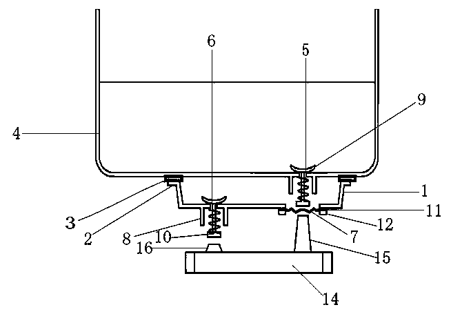
[0027] refer to Figure 1-3 , a humidifier parallel water valve structure, including a valve box 1, the top outer wall of the valve box 1 is welded with a fixed ring 2, and the top outer wall of the fixed ring 2 is welded with a seal 3, and the seal 3 is welded to The bottom outer wall of the water tank 4 of the humidifier, the bottom of the water tank 4 is provided with a first water outlet 5, the bottom of the valve box 1 is provided with a second water outlet 6 and a first through hole 7, and the first through hole 7 is provided with Directly below the first water outlet 5, a fixed tube 8 is welded around the outer walls of the bottoms of the first water outlet 5 and the second water outlet 6, and the inner walls of the first water outlet 5 and the second water outlet 6 are No. 1 valve 9 and No. 2 valve 10 are respectively socketed, and the No. 1 valve 9 and No. 2 valve 10 are also socketed on the inner wall of the fixed cylinder 8, and the outer wall around the bottom of t...

Embodiment 2

[0034] refer to Figure 4 , a humidifier parallel water valve structure, the connection between the sealing member 3 and the water tank 4 is replaced by a detachable clamping method from welding, and the top outer wall of the sealing member 3 is provided with a first A protruding ring 19 and a first groove 20, the corresponding positions of the bottom outer wall of the water tank 4 are provided with a second groove 21 and a second protruding ring 22, the first protruding ring 19 and the second groove 21, and Both the first groove 20 and the second protruding ring 22 can be clamped together and both are interference fit.

[0035] Working principle: The connection method between the sealing member 3 and the water tank 4 is replaced by a detachable clamping method from a welding method, the first protruding ring 19 and the second groove 21, and the first groove 20 and the The second protruding rings 22 are snapped together and have an interference fit, which is convenient for di...


PUM


Abstract

The invention discloses a parallel type lower water valve structure of a humidifier and a combined use mode thereof. The structure comprises valve boxes; multiple valve boxes can be provided; the multiple valve boxes are arrayed and laminated; a floater is arrayed with valve ejecting columns corresponding to lower water ports in number; the heights of the valve ejecting columns are reduced in sequence from right to left; and when two adjacent valve boxes are laminated, the valve boxes on the lower sides totally cover second lower ports of the valve boxes on the upper sides thereof, and first lower water ports of the valve boxes on the upper sides are exposed beyond the covering range of the valve boxes on the lower side.

Description

technical field [0001] The invention belongs to the technical field of humidifiers, and in particular relates to a humidifier parallel drain valve structure and its combined use. Background technique [0002] The existing top-filling ultrasonic humidifier (referred to as "top-filling humidifier") can directly open the water tank cover, thereby pouring water into the water tank from top to bottom to add water. This convenient operation method makes the top-filling humidifier obtain Loved by the majority of users. [0003] In the prior art, the bottom of the water tank of the upper water humidifier is provided with a water outlet, and a control valve is provided at the water outlet to achieve the purpose of controlling water supply, and the control valve is connected with a float control device, which can be opened or closed as required. Close the control valve. However, if the control valve or the float control device leaks water or fails during use, water will overflow int...

Claims


Application Information

Patent Timeline
Patent Type & Authority Applications(China)
IPC IPC(8): F24F6/12F24F13/00
CPCF24F6/12F24F13/00
Inventor 刘东方王慧明曹璐
Owner BEIJING YADU ENVIRONMENTAL PROTECTION TECH
Why Eureka
Try Eureka