Heat energy driving type pacemaker

A pacemaker and driving technology, applied in the field of medical devices, can solve the problems of the physical and mental and economic burden of patients, the complex structure of the pacemaker, and the difficulty of maintenance, so as to reduce the risk and economic burden of re-operation, compact structure, and easy maintenance. handy effect

Pending Publication Date: 2020-05-01
TIANJIN CHEST HOSPITAL
View PDF0 Cites 0 Cited by
  • Summary
  • Abstract
  • Description
  • Claims
  • Application Information

AI Technical Summary

Problems solved by technology

At present, the battery in the pacemaker is usually a lithium-iodine battery enclosed in a titanium alloy shell. When the battery is exhausted, the patient needs to undergo another operation to replace the battery before continuing to

Method used


Image

  • Heat energy driving type pacemaker
  • Heat energy driving type pacemaker
  • Heat energy driving type pacemaker

Examples


Embodiment 1

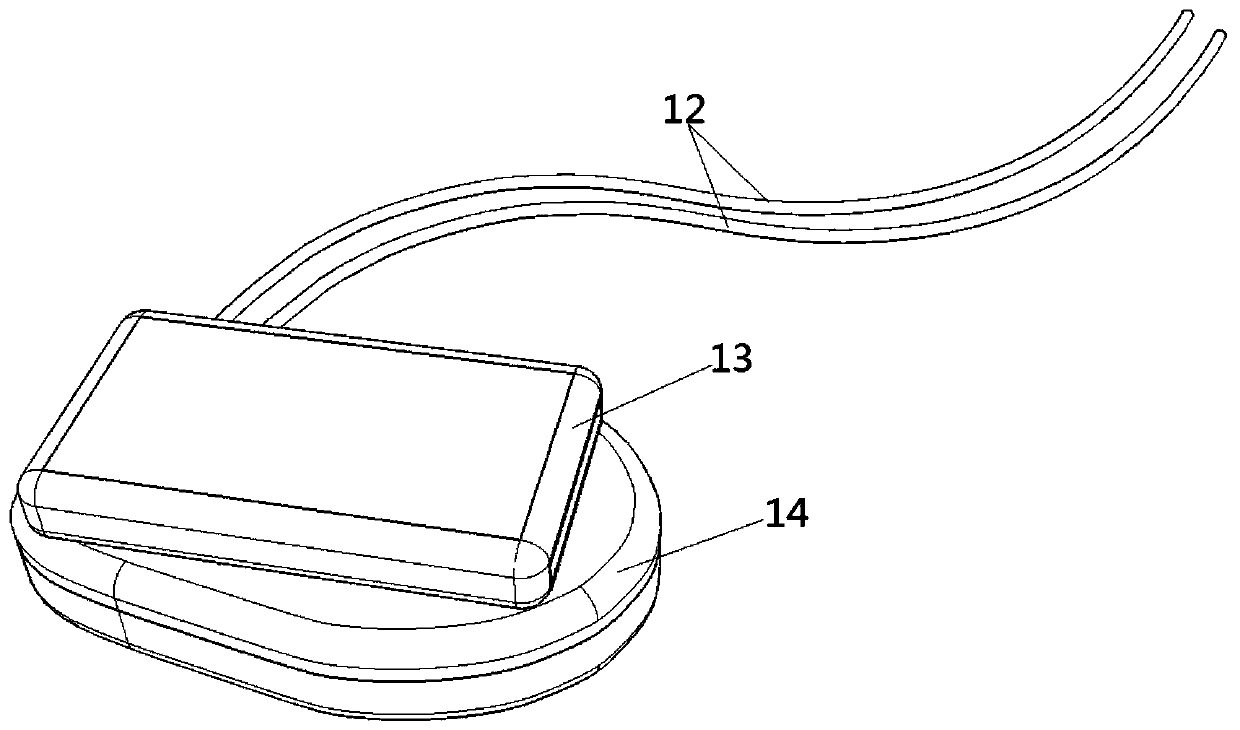
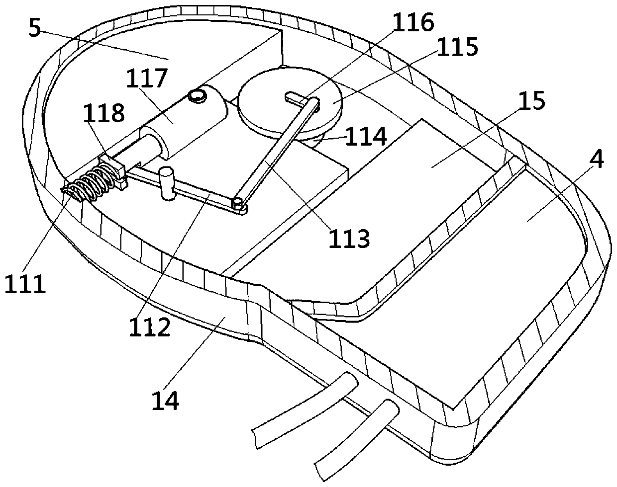
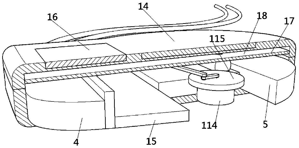
[0037] like Figure 1-Figure 5 , Figure 7-Figure 10 As shown, a heat-driven pacemaker includes: a power generation module 1, a control module 4, a battery module 5, and a power storage module 15. The power generation module 1 and the power storage module 15 are electrically connected to generate an AC pulse signal, The power generation module 1 includes a generator 114 , a rotating disc 115 , a link mechanism and a telescopic rod 117 , the generator 114 is connected to the link mechanism through the rotating disc 115 , and the link mechanism is connected to the telescopic rod 117 .

[0038] Further, the link mechanism includes a first link 112, a second link 113, and a third link 116, the generator 114 is fixedly installed on the pacemaker casing 14; the rotating disk 115 is fixedly installed on the On the motor shaft of the generator 114; the third connecting rod 116 is connected to the rotating disk 115 through the rotating shaft, and the rotating shaft is located at the c...

Embodiment 2

[0044] like Figure 1-Figure 4 , Figure 6-Figure 10 As shown, a heat-driven pacemaker includes a power generation module 1, a control module 4, a battery module 5, and a power storage module 15. The power generation module 1 and the power storage module 15 are electrically connected to generate an AC pulse electric signal. The power generation module 1 includes a generator 114 , a rotating disc 115 , a link mechanism and a telescopic rod 117 , the generator 114 is connected to the link mechanism through the rotating disc 115 , and the link mechanism is connected to the telescopic rod 117 .

[0045] Further, the linkage mechanism includes a first linkage 112, a second linkage 113, and a third linkage 116', and the rotating disc 115 is fixedly mounted on the motor shaft of the generator 114; the power generation module 1 also Including the third connecting rod 116, installed on the rotating disc 115 through the rotating shaft, the rotating shaft is located on the center of the...


PUM


Abstract

The invention discloses a heat energy driving type pacemaker, which comprises a pacemaker shell. A power generation module, a power storage module and a control module are arranged in the pacemaker shell. The power generation module is electrically connected with the power storage module, and AC pulse electric signals are generated; the power generation module comprises a power generator, the power generator is connected with a rotating disc, the rotating disc is connected with a telescopic rod through a connecting rod mechanism, an elastic piece is connected between the telescopic rod and theinner wall of the pacemaker shell, and the power generator drives the telescopic rod to stretch out and draw back and compresses or stretches out a spring through the rotating disc and the connectingrod mechanism. The charging device is adsorbed above the pacemaker shell through an adsorption device. Thus, the problem that the battery life of an existing pacemaker is limited is solved.

Description

technical field [0001] The invention relates to the field of medical devices, in particular to a heat-driven pacemaker. Background technique [0002] Pacemaker, also called pulse generator. What people usually call a pacemaker refers to the entire pacing system. The pacing system consists of a pacemaker, a pacing electrode lead and a program controller, wherein the pacemaker and the pacing electrode lead are implanted into the human body. A pacemaker consists of circuitry and batteries housed in a metal box. At present, pacemakers can be mainly divided into cardiac pacemakers, brain pacemakers, and laryngeal pacemakers. [0003] Existing pacemakers all need to be implanted in the body and need batteries for power supply. At present, the battery in the pacemaker is usually a lithium-iodine battery enclosed in a titanium alloy shell. When the battery is exhausted, the patient needs to undergo another operation to replace the battery before continuing to use the pacemaker, ...

Claims


Application Information

Patent Timeline
IPC IPC(8): H02J7/32H02J7/34A61N1/375A61N1/378
CPCA61N1/37512A61N1/3787H02J7/32H02J7/345
Inventor 张楠马玥梁宝凤刘维来君
Owner TIANJIN CHEST HOSPITAL
Why Eureka
Try Eureka