Electrodes for intra-cardiac pacemaker

A pacemaker and electrode technology, applied in the field of implantable medical equipment, can solve problems such as heart conduction diseases or abnormalities that cannot be completely solved

Pending Publication Date: 2020-05-01
MEDTRONIC INC
View PDF19 Cites 1 Cited by
  • Summary
  • Abstract
  • Description
  • Claims
  • Application Information

AI Technical Summary

Problems solved by technology

Single-chamber pacing and sensing may adequately address patient needs in some patients, however, single-chamber pacing and sensing may not fully address cardiac conduction disease or abnormalities in all patients

Method used


Image

  • Electrodes for intra-cardiac pacemaker
  • Electrodes for intra-cardiac pacemaker
  • Electrodes for intra-cardiac pacemaker

Examples


Embodiment Construction

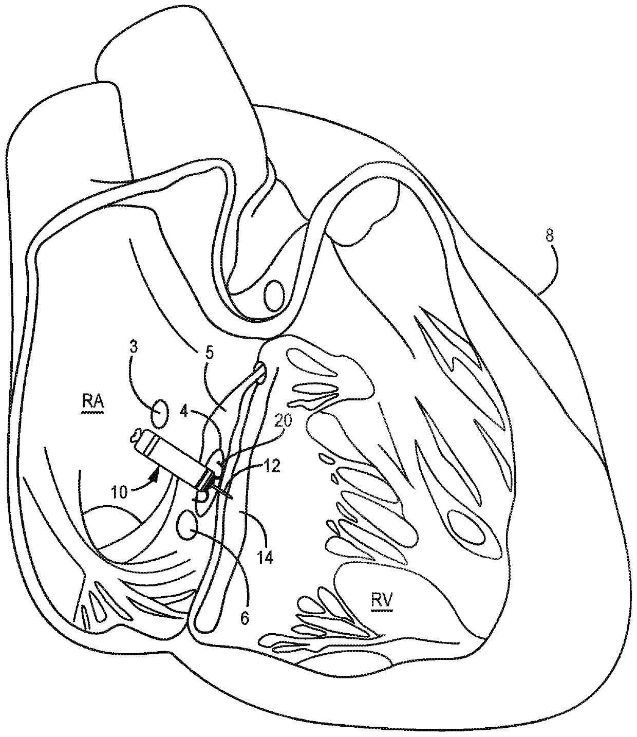
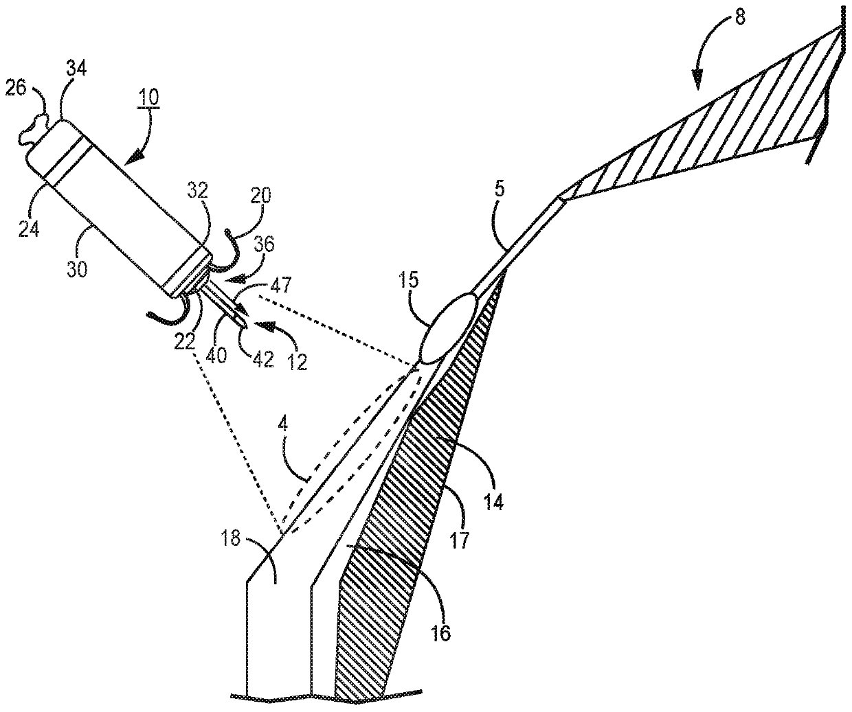
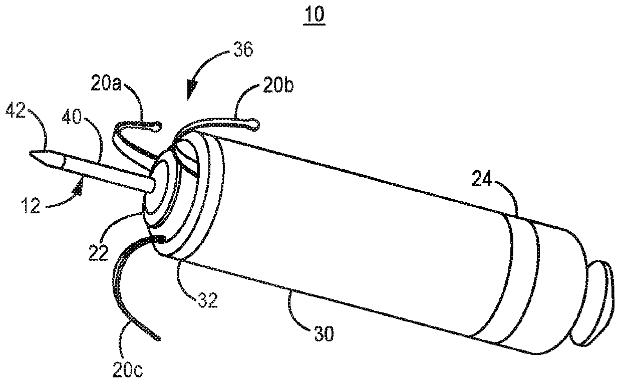
[0034] figure 1 It is a conceptual diagram of a dual-chamber intracardiac pacemaker 10 implanted in a patient's heart 8 . Pacemaker 10 is shown implanted in the right atrium (RA) of patient's heart 8 in target implantation zone 4 . The pacemaker 10 includes a fixation member 20 that anchors the distal end of the pacemaker against the atrial endocardium in the target implantation region 4 . The target implantation region 4 may be located between the bundle of His 5 and the coronary sinus 6 and may be adjacent to the tricuspid valve 3 . The pacemaker 10 may be a leadless pacemaker comprising a dart electrode 12 having a straight axis extending from the distal end of the pacemaker 10 through the atrial myocardium and central fibrous body, and Enters the ventricular myocardium 14 or extends along the ventricular septum without completely penetrating the ventricular endocardial or epicardial surface. Dart electrode 12 carries an electrode at the distal end of the shaft for posit...


PUM


Abstract

A pacemaker has a housing and a therapy delivery circuit enclosed by the housing for generating pacing pulses for delivery to a patient's heart. An electrically insulative distal member is coupled directly to the housing and at least one non-tissue piercing cathode electrode is coupled directly to the insulative distal member. A tissue piercing electrode extends away from the housing.

Description

[0001] Cross References to Related Applications [0002] This application claims the benefit of U.S. Provisional Patent Application Serial No. 62 / 559,106, filed September 15, 2017, and U.S. Application Serial No. 62 / 583,075, filed November 8, 2017, the entire contents of which are hereby incorporated by reference. technical field [0003] The present disclosure relates generally to implantable medical devices and in particular to intracardiac pacemakers. Background technique [0004] The cardiac conduction system includes the sinoatrial (SA) node, atrioventricular (AV) node, His bundle, bundle branches, and Purkinje fibers. The heartbeat is initiated in the SA section, which serves as the heart's natural "pacemaker". Electrical impulses initiated by the SA node cause the atrial myocardium to contract. The signal is conducted to the ventricles via the AV node, which inherently delays conduction to allow the atria to stop contracting before the ventricles begin contracting, ...

Claims


Application Information

Patent Timeline
IPC IPC(8): A61N1/375
CPCA61N1/37518A61N1/3756A61N1/0573A61N1/368A61N1/37512A61N1/0504A61N2001/058A61N1/3621A61N1/3752
Inventor Z·杨B·L·多兰X·陈T·A·安德森B·施特格曼M·费尔贝克M·D·埃根
Owner MEDTRONIC INC
Why Eureka
Try Eureka