
Twin-spool turbojet engine having low-pressure shaft thrust bearing positioned in exhaust casing

A turbojet, low pressure turbine technology used in engine components, engine functions, machines/engines, etc.

Active Publication Date: 2020-05-01
SAFRAN AIRCRAFT ENGINES SAS
View PDF4 Cites 0 Cited by
  • Summary
  • Abstract
  • Description
  • Claims
  • Application Information

AI Technical Summary

Problems solved by technology

[0017] However, the space requirement of the first bearing BP#1 makes it difficult to integrate this bearing into the center of the low pressure compressor 31

Method used


Image

  • Twin-spool turbojet engine having low-pressure shaft thrust bearing positioned in exhaust casing
  • Twin-spool turbojet engine having low-pressure shaft thrust bearing positioned in exhaust casing
  • Twin-spool turbojet engine having low-pressure shaft thrust bearing positioned in exhaust casing

Examples


Embodiment Construction

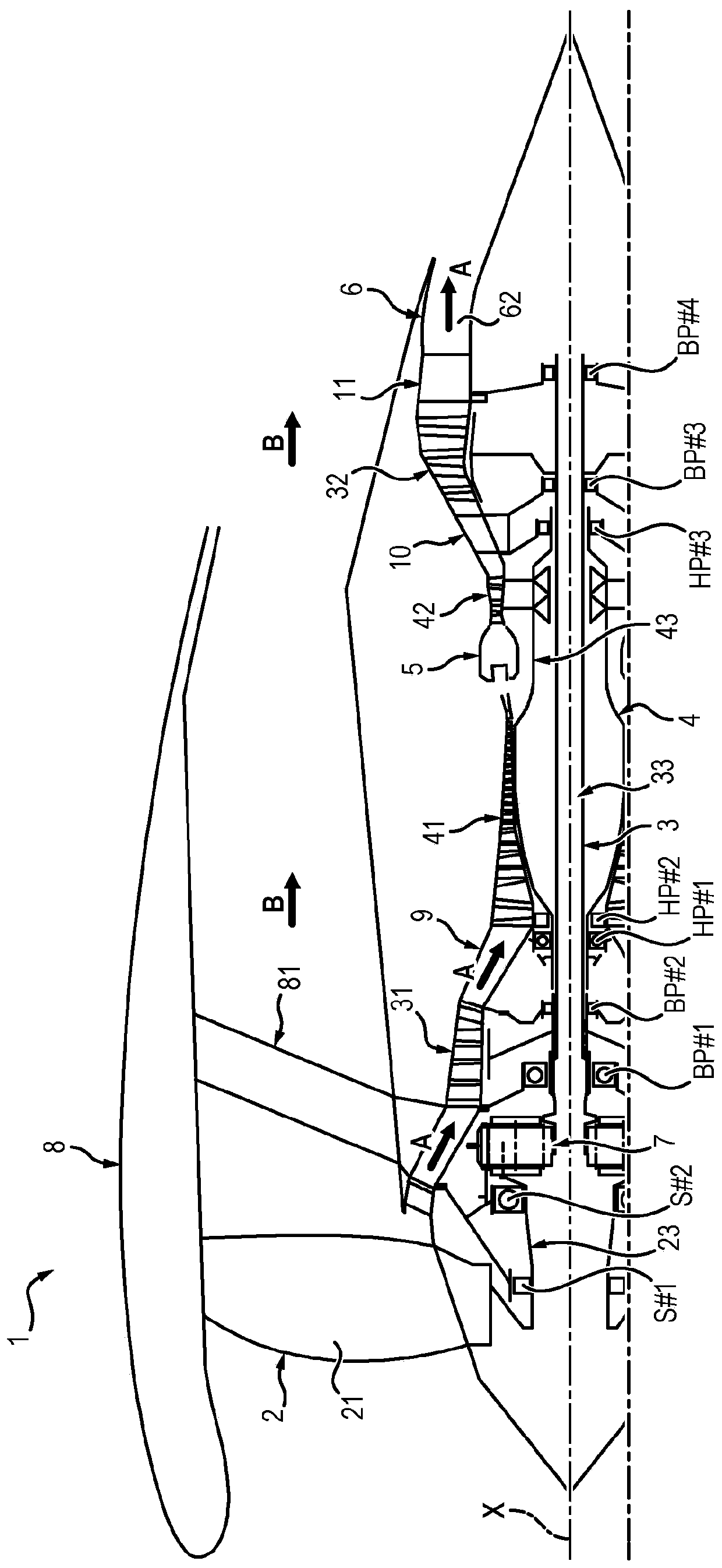
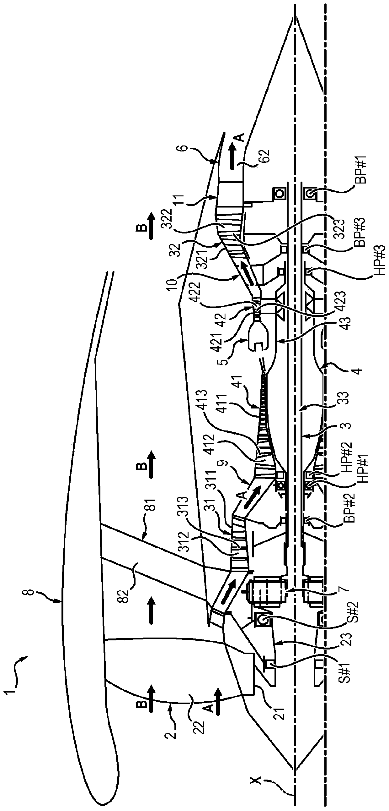
[0070] exist image 3 and Figure 4 , a turbojet engine 1 is shown comprising a fan 2 , a low-pressure swivel 3 , a high-pressure swivel 4 , a combustion chamber 5 and an exhaust nozzle 6 .

[0071] The fan 2 comprises a fan disc 21 provided at its perimeter with fan blades 22 which, when rotating, drive air to flow in the primary and secondary flow spaces of the turbojet 1 .

[0072] The low-pressure swivel 3 includes a low-pressure compressor 31 , a low-pressure turbine 32 , and a low-pressure shaft 33 coupling the low-pressure turbine 32 to the low-pressure compressor 31 .

[0073] The high-pressure swivel 4 includes a high-pressure compressor 41 , a high-pressure turbine 42 , and a high-pressure shaft 43 coupling the high-pressure turbine 42 to the high-pressure compressor 43 .

[0074] The low-pressure shaft 33 extends inside the high-pressure shaft 43 . The low pressure shaft 33 and the high pressure shaft 43 are coaxial. The low-pressure shaft 33 and the high-pressur...


PUM


Abstract

The invention relates to a twin-spool turbojet engine (1) comprising: a low-pressure spool (3), comprising a low-pressure compressor (31), a low-pressure turbine (32) and a low-pressure shaft (33) connecting the low-pressure turbine (32) to the low-pressure compressor (31), an exhaust casing (11) through which exhaust gases flow downstream of the low-pressure turbine (32), the turbojet engine (1)being characterized in that it further comprises a low-pressure shaft thrust bearing (BP#1) comprising an inner ring and an outer ring, one of the rings being fixed to the low-pressure shaft (33) andthe other of the rings being fixed to the exhaust casing (11).

Description

technical field [0001] The present invention relates to a twin-swivel turbojet engine, more particularly to a twin-flow twin-swivel geared turbojet engine (turbofan engine) with a high bypass ratio. Background technique [0002] 1 and 2 schematically show an example of a twin-flow twin-rotor (corps) geared turbojet engine 1 . [0003] The turbojet engine 1 shown in these figures comprises a fan 2 , a low-pressure swivel 3 , a high-pressure swivel 4 , a combustion chamber 5 and an exhaust nozzle 6 . [0004] The high-pressure swivel 4 includes a high-pressure compressor 41 , a high-pressure turbine 42 , and a high-pressure shaft 43 coupling the high-pressure turbine 42 to the high-pressure compressor 41 . [0005] The low-pressure swivel 3 includes a low-pressure compressor 31 , a low-pressure turbine 32 , and a low-pressure shaft 33 that couples the low-pressure turbine 32 to the low-pressure compressor 31 and extends inside a high-pressure shaft 43 . [0006] The high-pre...

Claims


Application Information

Patent Timeline
Patent Type & Authority Applications(China)
IPC IPC(8): F02C7/06F02K3/06F01D25/16
CPCF01D25/168F02K3/06F02C7/06F05D2220/326F05D2240/52F05D2260/40311F05D2220/327Y02T50/60F02K3/04F05D2220/323
Inventor 吉拉姆·帕特里斯·库比亚克尼尔斯·爱德华·罗曼·博尔多尼米歇尔·吉尔伯特·罗兰·布罗罗曼·吉拉姆·古维列阿诺·尼古拉斯·内格里娜塔莉·诺瓦克斯基
Owner SAFRAN AIRCRAFT ENGINES SAS
Learn More