
Air intake assembly for centrifugal blower system and fuel cell incorporating same

A technology of centrifugal blower and air intake components, which is applied in the direction of fuel cells, fuel cell additives, and components of pumping devices for elastic fluids, etc. It can solve the problem of destroying fuel cell stack oxidation, etc., and achieve the effect of improving response time

Pending Publication Date: 2020-05-01
WATT FUEL CELL CORP
View PDF28 Cites 0 Cited by
  • Summary
  • Abstract
  • Description
  • Claims
  • Application Information

AI Technical Summary

Problems solved by technology

Exposure of fuel cell components to this additional air or exhaust can lead to oxidation that can damage the fuel cell stack

Method used


Image

  • Air intake assembly for centrifugal blower system and fuel cell incorporating same
  • Air intake assembly for centrifugal blower system and fuel cell incorporating same
  • Air intake assembly for centrifugal blower system and fuel cell incorporating same

Examples


Embodiment Construction

[0034] The present disclosure can be understood more readily by reference to the following detailed description of the disclosure taken in conjunction with the accompanying drawings that form a part hereof. It is to be understood that the present disclosure is not to be limited to the specific apparatus, methods, conditions or parameters described and / or illustrated herein, and that the terminology used herein is for the purpose of describing particular embodiments by way of example only, and is not intended to be limiting of the claims. public content.

[0035] Likewise, as used in the specification and the appended claims, the singular forms "a" and "the" include plural referents and references to specific values ​​include at least that specific value unless the context clearly dictates otherwise. Ranges can be expressed herein as from "about" or "approximately" one particular value, and / or to "about" or "approximately" another particular value. When such a range is express...


PUM


Abstract

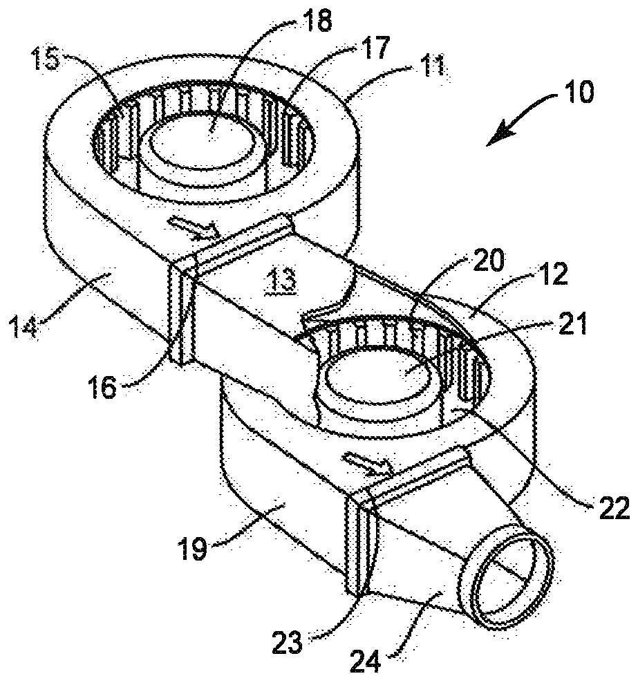
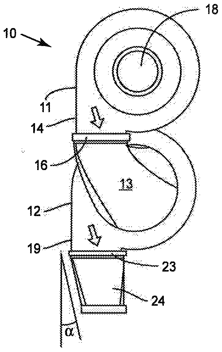
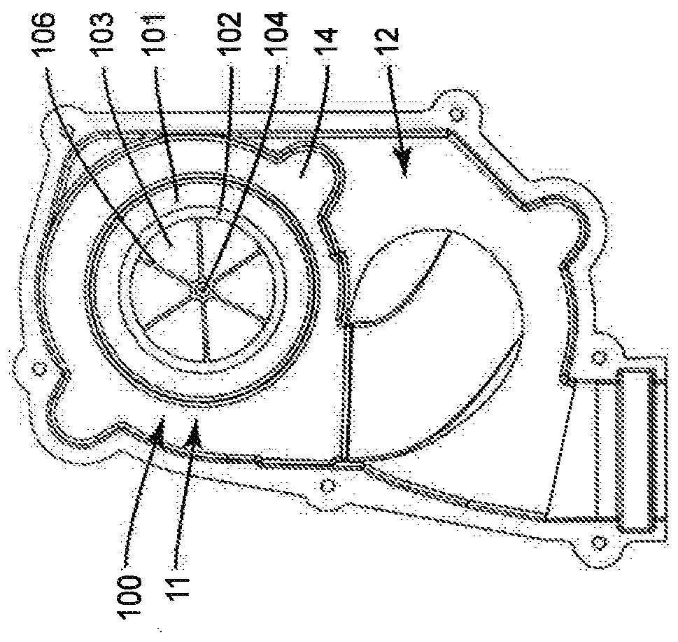
An air intake assembly for a centrifugal blower having a casing having an axial inlet and a radial outlet, an impeller disposed within the casing for drawing a gaseous medium at a first pressure intothe axial inlet and expelling gaseous medium at a second higher pressure through the radial outlet, and a motor for driving the impeller, including an air intake assembly casing having an air inlet and an air outlet, the air outlet connectable to the axial inlet of the blower casing of the centrifugal blower, and a check valve mounted within the air intake assembly casing positioned to permit airflow from the air inlet through the air intake assembly casing to the air outlet and prevent air flow from the air outlet through the air intake assembly casing to the air inlet.

Description

technical field [0001] The present invention relates to a centrifugal blower and a fuel cell including the centrifugal blower, and more particularly, to an air intake assembly for a centrifugal blower. Background technique [0002] A centrifugal blower or centrifugal fan is a well known type of device for providing flow or motion of a gaseous medium. A common type of centrifugal blower includes a housing having an axially directed gas inlet and a radially directed gas outlet; an impeller disposed within the housing for drawing gas at a first pressure into the A second, higher pressure gas exits through the outlet; and a motor for driving (ie rotating) the impeller. Variations of this general type of centrifugal blower are disclosed, for example, in US Patent Nos. 4,917,572; 5,839,879; 6,877,954; 7,061,758; 7,351,031; 7,887,290; [0003] Centrifugal blowers have been disclosed in single unit and multiple independent unit configurations as components of cooling systems for c...

Claims


Application Information

Patent Timeline
Patent Type & Authority Applications(China)
IPC IPC(8): F04D17/16F04D25/14F04D29/42F04D29/70H01M8/04089
CPCF04D17/16F04D25/14F04D29/4213F04D29/703H01M8/04089H01M8/04201H01M2008/1293Y02E60/50F04D29/706F16K15/148F04D25/166
Inventor C.M.芬纳蒂P.德瓦尔德
Owner WATT FUEL CELL CORP
Learn More