
Cutting equipment for UAV shell board

A technology for cutting equipment and shell panels, applied in the field of unmanned aerial vehicles, which can solve problems such as single function

Active Publication Date: 2021-04-23
广东卓柏信息科技有限公司
View PDF4 Cites 0 Cited by
  • Summary
  • Abstract
  • Description
  • Claims
  • Application Information

AI Technical Summary

Problems solved by technology

[0002] The cutting equipment of the UAV shell plate is a commonly used equipment in the field of UAV, but the cutting equipment of the general UAV shell plate has a single function

Method used


Image

  • Cutting equipment for UAV shell board
  • Cutting equipment for UAV shell board
  • Cutting equipment for UAV shell board

Examples


specific Embodiment approach 1

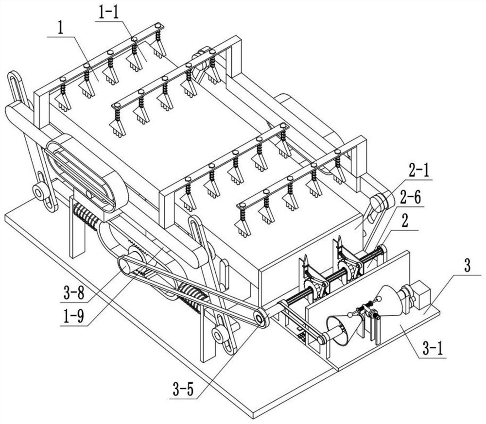
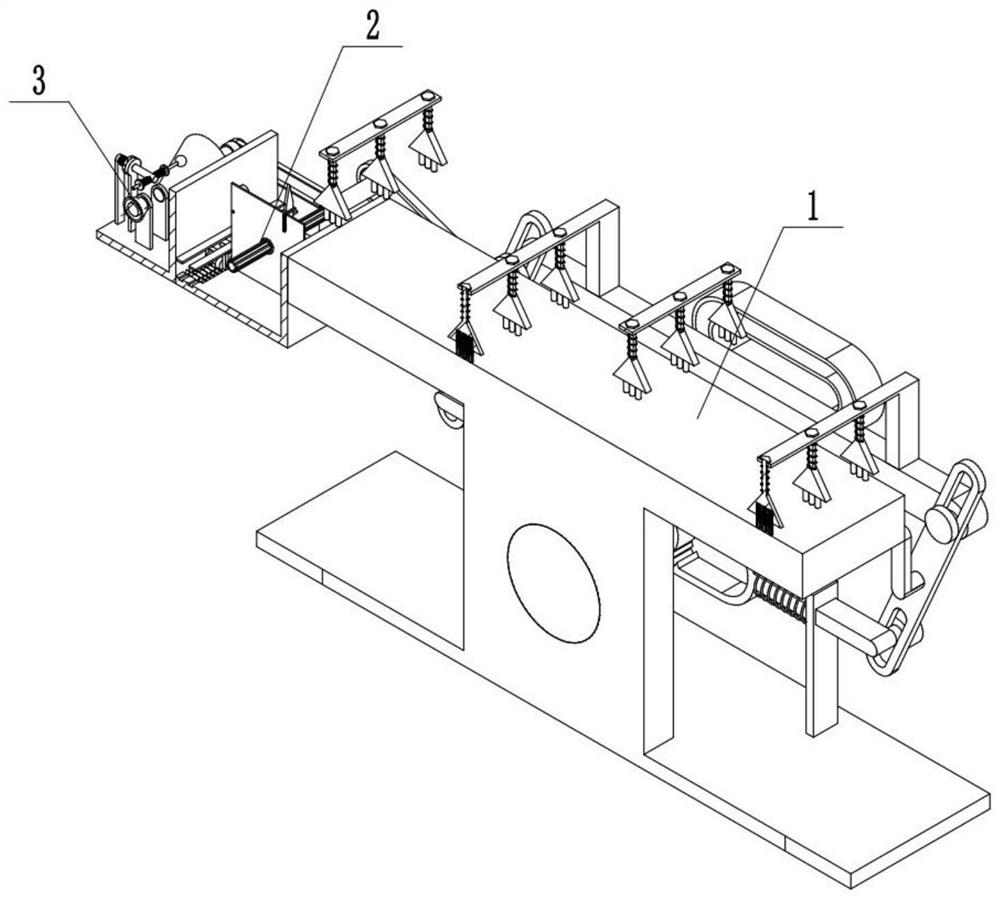
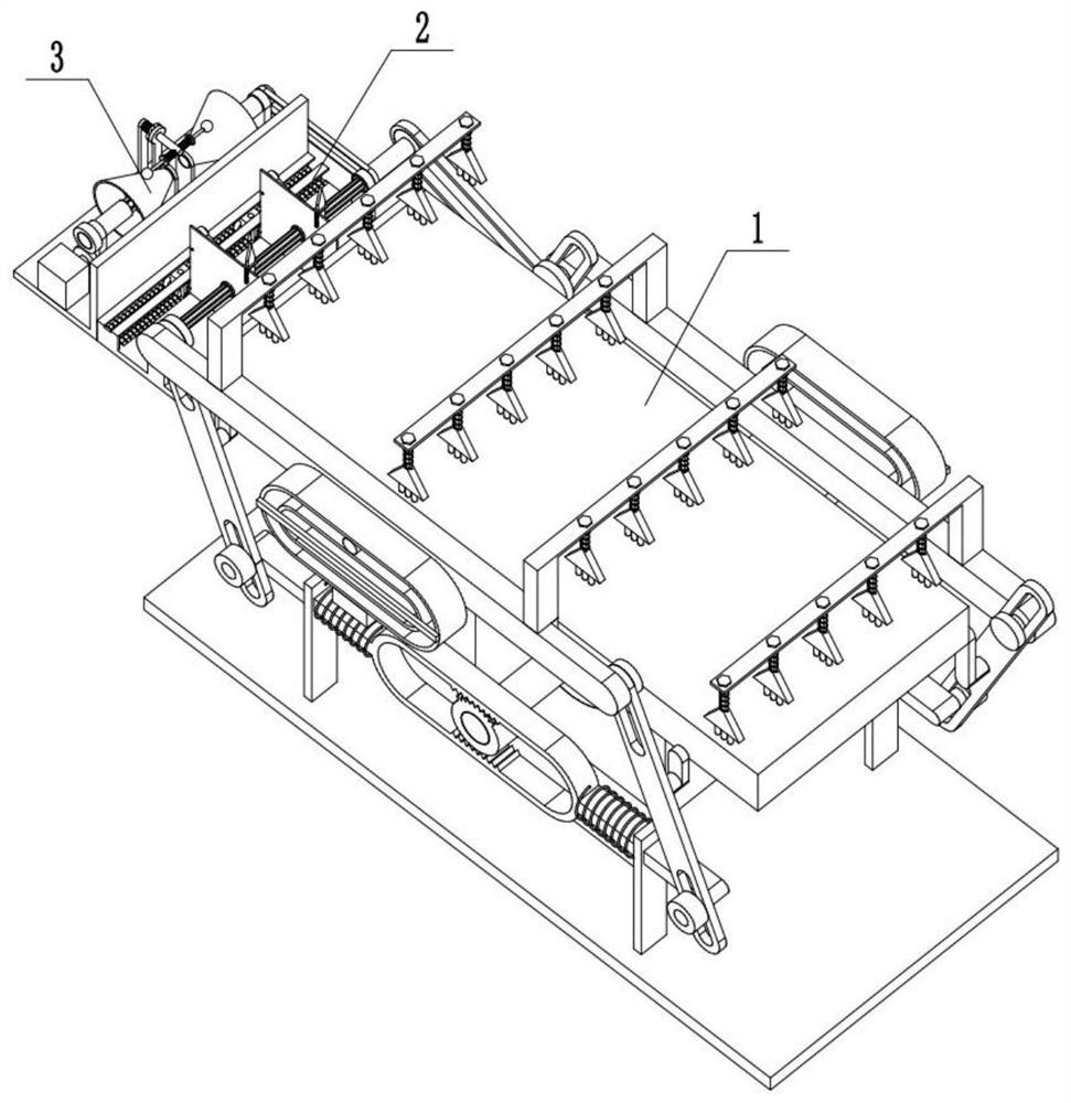
[0031] Combine below Figure 1-15 Describe this embodiment, a kind of cutting equipment of unmanned aerial vehicle shell plate, comprise stepping transportation assembly 1, cutting assembly 2, power source assembly 3, it is characterized in that: described stepping transportation assembly 1 and cutting assembly The body 2 is connected, the cutting assembly 2 is connected with the power source assembly 3, and the stepping transport assembly 1 is connected with the power source assembly 3.

specific Embodiment approach 2

[0033] Combine below Figure 1-15 This embodiment will be described. This embodiment will further explain the first embodiment. The stepping transport assembly 1 includes an upper end plate surface 1-1, a bottom plate 1-2, an auxiliary bracket one 1-3, an auxiliary bracket two 1-4, Auxiliary hinge rod 1-5, auxiliary hinge rod 2 1-6, bracket 1-7, bracket spring 1-8, auxiliary rotating rod 1-9, half gear 1 1-10, half gear 2 1-11, auxiliary cross Rod one 1-12, drive hinge rod one 1-13, transverse carriage one 1-14, drive hinge rod two 1-15, limit frame one 1-16, limit groove one 1-17, auxiliary cross bar two 1-18, driving hinge rod three 1-19, horizontal carriage two 1-20, driving hinge rod four 1-21, limit frame two 1-22, limit slot two 1-23, push rod 1-24 , push the push rod 1-25, press the terminal 1-26, the middle end push spring one 1-27, the middle end push spring two 1-28, the inner terminal 1-29, the upper end plate surface 1-1 and the bottom plate 1- 2 Fixed connection...

specific Embodiment approach 3

[0036] Combine below Figure 1-15Describe this embodiment, this embodiment will further explain the first embodiment, the cutting assembly 2 includes a cutting bottom plate 2-1, a bracket 2-2, a side wall slot 2-3, and a side wall rectangular slot 2-4 , limit bracket 2-5, drive shaft 2-6, cutting bracket 2-7, flower wheel 2-8, flower wheel bracket 2-9, matching sleeve 2-10, cutting blade 2-11, driving hinge rod 2 -12, matching roller 1 2-13, matching roller 2 2-14, middle end slider 2-15, middle end sliding column 2-16, middle end sleeve spring 2-17, matching hinge rod 2-18, matching rotor 2-19, with push spring 2-20, with rotating column 2-21, side wall sliding column 2-22, side wall sliding column push spring 2-23, rectangular boss 2-24, N-shaped frame 2-25, Roller 2-26, mid-end clamping rod 2-27, mid-end push spring 2-28, bracket 1 2-2 is fixedly connected with cutting base plate 2-1, side wall slot 2-3, side wall rectangular slot 2- 4 Set on the cutting base plate 2-1, t...


PUM


Abstract

The present invention relates to the field of unmanned aerial vehicle, more specifically a kind of cutting equipment of unmanned aerial vehicle shell plate. It can realize the step-by-step transportation of the UAV shell plate, and then facilitate the improvement of the transportation rate of the UAV shell plate; it can realize the cutting of the UAV shell plate and can adjust the specifications that can be cut according to the actual situation; it can be based on The actual situation adjusts the transmission ratio of the device during processing. Including the stepping transport assembly, the cutting assembly, and the power source assembly, the output shaft 2 is driven to move through the output belt 1, and then drives the drive shaft to rotate, and at the same time, the output shaft 3 is driven to move through the output belt 2, and then drives the auxiliary The rotating rod rotates; the transmission ratio output by the output shaft 1 can be adjusted according to the actual situation, and the matching rod 1 is manually rotated to drive the auxiliary transmission rod to rotate through the matching rod 1.

Description

technical field [0001] The present invention relates to the field of unmanned aerial vehicle, more specifically a kind of cutting equipment of unmanned aerial vehicle shell plate. Background technique [0002] The cutting equipment of the UAV shell plate is a commonly used equipment in the field of UAV, but the cutting equipment of the general UAV shell plate has a single function. Contents of the invention [0003] The purpose of the present invention is to provide a cutting device for the UAV shell plate, which can realize the step-by-step transportation of the UAV shell plate, and then facilitate the improvement of the transportation rate of the UAV shell plate; The cutting of the board can also adjust the specifications that can be cut according to the actual situation; the transmission ratio of the device during processing can be adjusted according to the actual situation. [0004] The purpose of the present invention is achieved through the following technical solut...

Claims


Application Information

Patent Timeline
Patent Type & Authority Patents(China)
IPC IPC(8): B26D7/06B26D7/02
CPCB26D7/025B26D7/06
Inventor 钟聪明
Owner 广东卓柏信息科技有限公司
Learn More