Method for manufacturing large caliber aspherical mirror

A technology of aspheric mirror and manufacturing method, which is applied in the optical field using large-diameter aspheric mirrors, can solve the problems of difficult manufacturing, long cycle, and high cost, and achieve the effects of shortening the manufacturing cycle, reducing the difficulty of processing and testing, and alleviating requirements

Inactive Publication Date: 2010-04-21
SUZHOU UNIV
View PDF2 Cites 0 Cited by
  • Summary
  • Abstract
  • Description
  • Claims
  • Application Information

AI Technical Summary

Problems solved by technology

The precision requirements of the compensator are very high, so its manufacture itself is very difficult
Therefore, the manufacture of large-diameter aspheric mirrors always takes a long time and costs a lot

Method used


Image

  • Method for manufacturing large caliber aspherical mirror
  • Method for manufacturing large caliber aspherical mirror
  • Method for manufacturing large caliber aspherical mirror

Examples


Embodiment 1

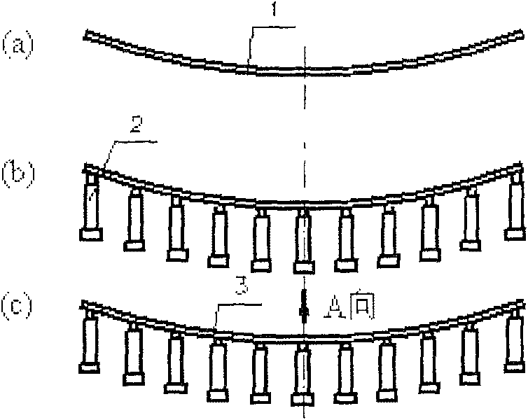
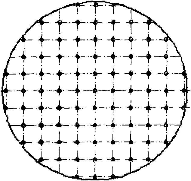
[0073] Embodiment 1: A kind of manufacturing method of large diameter aspheric mirror, see attached figure 1 , the specific steps are: (1) finish processing a qualified ultra-thin spherical mirror 1, (2) place it on the actuator assembly 2 to keep the radius and surface shape accuracy of the spherical mirror, (3) pass a certain number of regular arrangements The actuator exerts a displacement on the mirror surface, causing the mirror surface to be forcibly deformed and deformed into the required aspheric mirror 3 . attached figure 2 A schematic diagram of the actuator arrangement using a square uniform arrangement is shown.

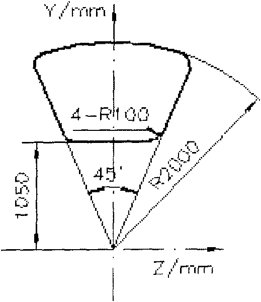
[0074] See attached image 3 As shown, the ultra-thin mirror is aspherically shaped. The equation of the aspheric surface is

[0075]

[0076] where c=1 / R 0 , R 0 =9760mm, k=-0.98. The material of the ultra-thin mirror is Zerodur, and its elastic modulus is 90.3×10 9 N / m 2 , Poisson's ratio is 0.24, the allowable stress is 10MPa, and the thic...

Embodiment 2

[0105] Embodiment 2: Comparison of asphericity gradient conversion rate method and other arrangement methods.

[0106] Refer to the example of forming an aspheric surface of an ultra-thin mirror in Example 1 to compare the arrangement methods of the actuators.

[0107] In the case of no gravity, the actuator layout, surface shape residual diagram and von Mises stress moiré diagram obtained by using the asphericity gradient transformation rate method are shown in Figure 13 ~ Figure 15 .

[0108] The actuator arrangement, surface residual and von Mises stress moiré diagram obtained by the square method are shown in Figure 21 ~ Figure 23 .

[0109] The actuator arrangement, surface residual and von Mises stress moiré diagram obtained by using the ring method to meet the surface accuracy are shown in Figure 24 ~ Figure 26 .

[0110] See Figure 27 ~ Figure 29 . Correction means that the actuators are spaced differently on the border than in the central area.

[0111] See...


PUM


Abstract

The invention discloses a production method of large aperture aspheric mirrors, comprising the step of: (1) calculating a best fitting sphere according to aspheric degree gradient method, machining and completing an ultra-thin spherical mirror according to the best fitting sphere; (2) obtaining an actuator distribution initial scheme, according to the aspheric degree gradient change rate method, to obtain the final solution of the actuator distribution and the forced displacement quantity of each actuator after optimization; (3) machining and completing an actuator component; (4) arranging thecompleted ultra-thin sphere mirror on the actuator component, adjusting the displacement quantity of the actuator to approach the ultra-thin sphere mirror to the designed best fitting sphere radius and figure accuracy; (5) according to the forced displacement quantity of each actuator obtained in the step (2), adjusting the displacement actuator to deform the sphere mirror into the demanded aspheric figure to obtain the large aperture aspheric mirror. The invention avoids the difficulty in the processing and checking of large aperture aspheric mirrors, to reduce processing and checking difficulty, reduce production period and reduce production cost.

Description

technical field [0001] The invention relates to a method for manufacturing an aspheric surface, in particular to a method for manufacturing a large-diameter aspheric mirror, which is particularly suitable for the optical field using the large-diameter aspheric mirror. Background technique [0002] In many fields of space optics, large-aperture aspheric primary reflectors are widely used. In order to achieve the highest possible ground resolution, increasing the aperture of the reflector is the most important way. However, with the increase of the caliber, the self-weight of the primary mirror increased sharply, which brought a series of technical problems. Therefore, the lightweight problem of the primary mirror has always been paid attention to by people. With the development of active optics technology, ultra-thin aspheric primary mirrors with active optics for surface shape control have emerged. The thickness of this mirror is about several millimeters, and the effecti...

Claims


Application Information

Patent Timeline
Patent Type & Authority Patents(China)
IPC IPC(8): G02B3/02G02B27/00G02B7/182
Inventor 曾春梅余景池
Owner SUZHOU UNIV
Why Eureka
Try Eureka