Wall corner lamp and building structure
A corner lamp and lamp body technology, applied in the direction of gas-proof/waterproof devices, lighting and heating equipment, lighting devices, etc., can solve the problems of high wiring costs, inconvenient installation and use, and inability to guarantee waterproof effects, etc., to achieve stable wiring, Good waterproof effect
- Summary
- Abstract
- Description
- Claims
- Application Information
AI Technical Summary
Problems solved by technology
Method used
Image

Examples
Embodiment 1
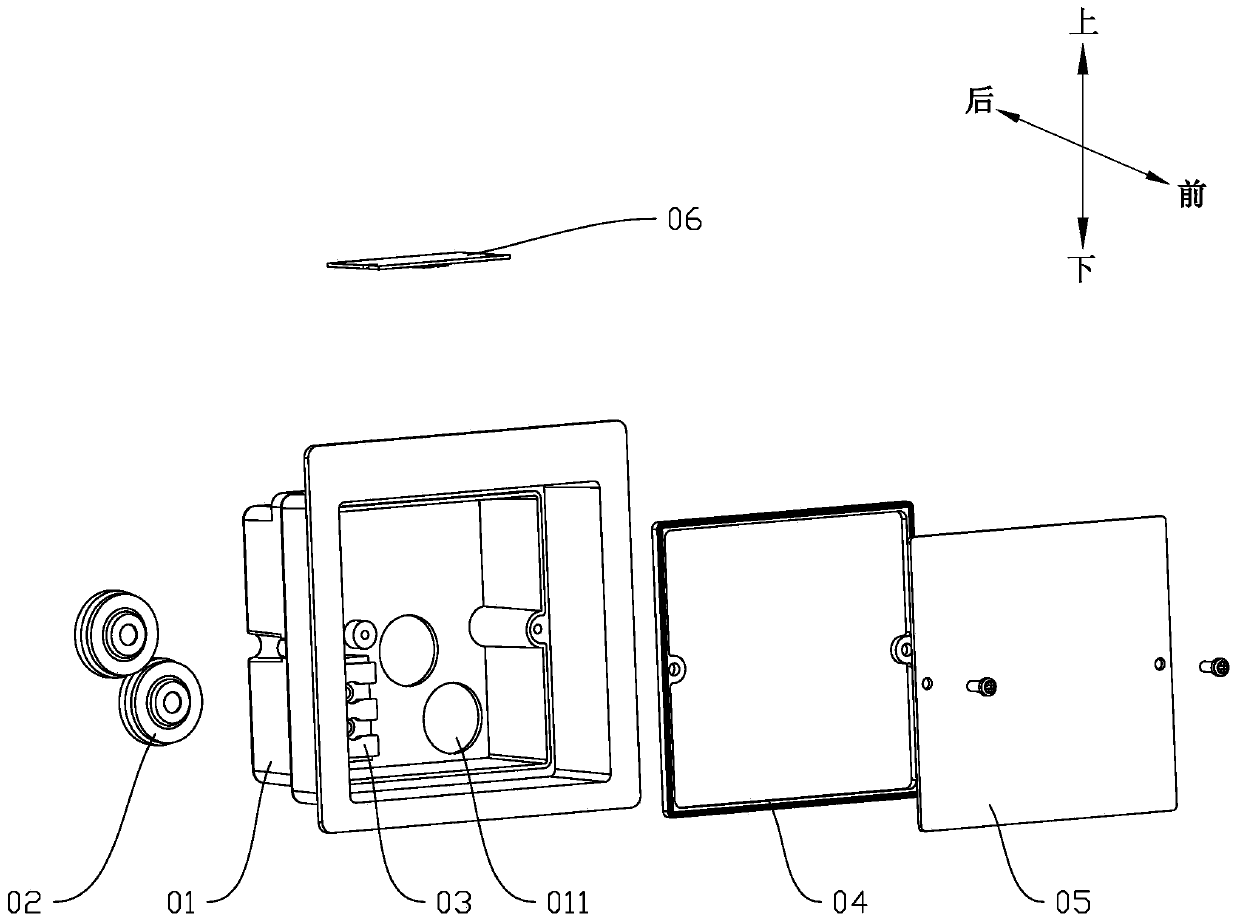
[0037] refer to figure 1 , shows an exploded schematic view of the first embodiment of the present invention. This embodiment provides a corner lamp, which includes a lamp body shell 01 , a first sealing ring 02 , a connection terminal 03 , a second sealing ring 04 , a cover plate 05 and a lamp plate 06 . The interior of the lamp body shell 01 defines a first cavity, and the lamp body shell 01 is provided with a first opening communicating with the first cavity and two wire holes 011 through which the power supply line enters and exits. At the front of the body shell 01, two wire holes 011 are opened on the back of the lamp body shell 01. The position of the wire holes 011 has no influence on the side wall of the lamp body shell 01, which is convenient for the lamp body shell 01 to be installed in the installation hole, and also Wire holes 011 can be opened on other surfaces of the lamp body shell 01 according to actual needs, or the number of wire holes 011 can be changed. ...
Embodiment 2
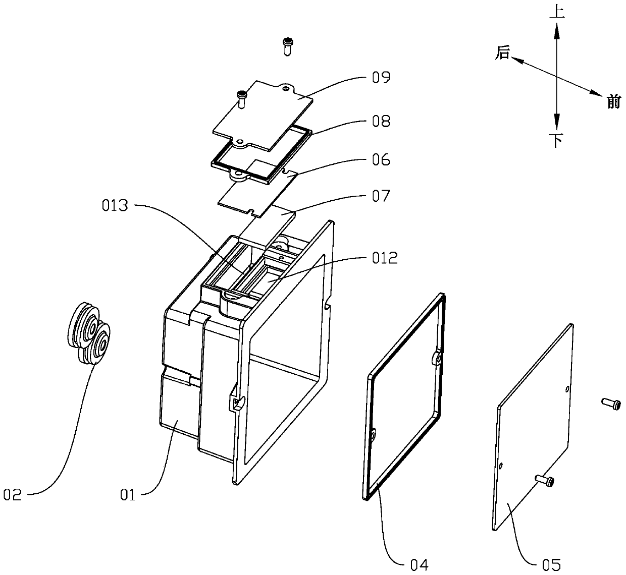
[0041] refer to figure 2 , shows an exploded schematic view of the second embodiment of the present invention. The difference between this embodiment and Embodiment 1 includes, but not limited to, a second cavity is defined outward on one side wall of the lamp housing 01, for example figure 2The upper side wall of the center, and add a transparent plate 07, a third sealing ring 08 and a lamp cover 09, the second cavity is provided with a light hole 012 and a wire groove 013, the second cavity and the first cavity pass through The light hole 012 communicates with the wire groove 013, and the second cavity is provided with a second outlet. The transparent plate 07 and the lamp plate 06 are installed in the second cavity sequentially from the second exit, the transparent plate 07 is covered on the light hole 012 and fixed at the light hole 012, so that the light generated by the lamp plate 06 can pass through. However, the transparent board 07 can be fixed by using glue, clam...
Embodiment 3
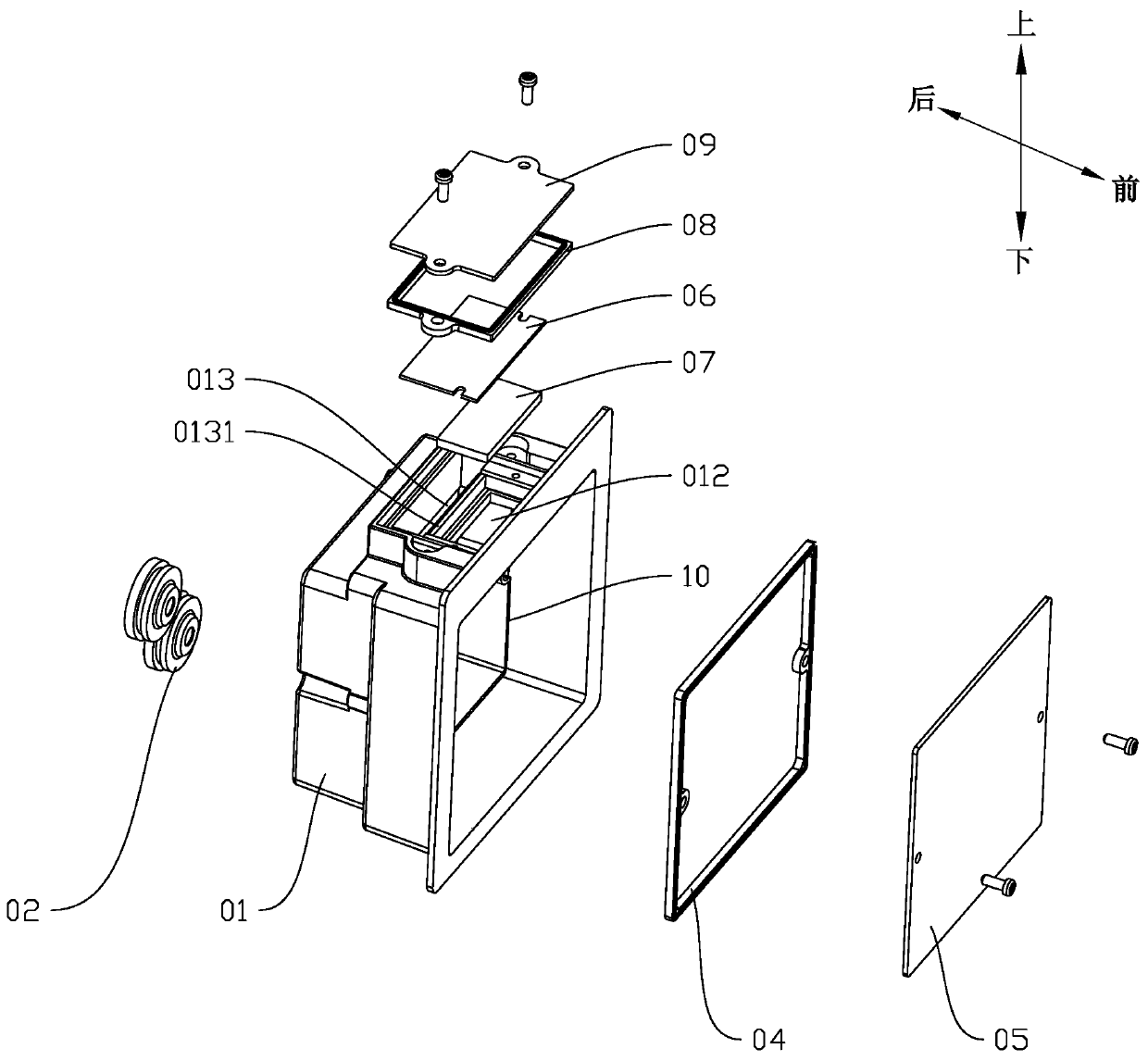
[0045] refer to image 3 with Figure 4 , showing an exploded schematic view of a third embodiment of the present invention and image 3 Schematic diagram of the structure of the second cavity on the middle lamp body shell. The difference between the present embodiment and the second embodiment includes but not limited to, the position of the crossbeam 0131 corresponding between the light hole 012 and the wire slot 013, the mounting platform 10 is provided on the surrounding side walls of the lamp body shell 01, and the second The sealing ring 04 and the cover plate 05 are installed on the mounting table 10 by screws or sealing glue, so that the part of the first cavity defined between the rear of the lamp body housing 01 and the cover plate 05 passes through the wire groove 013 and the second cavity. The two cavities are connected.
[0046] When the transparent plate 07 is fixed at the light hole 012, the space between the transparent plate 07 and the light hole 012 is sea...
PUM
 Abstract
Description
Claims
Application Information
 - R&D
- Intellectual Property
- Life Sciences
- Materials
- Tech Scout
- Unparalleled Data Quality
- Higher Quality Content
- 60% Fewer Hallucinations
Browse by: Latest US Patents, China's latest patents, Technical Efficacy Thesaurus, Application Domain, Technology Topic, Popular Technical Reports.
© 2025 PatSnap. All rights reserved.Legal|Privacy policy|Modern Slavery Act Transparency Statement|Sitemap|About US| Contact US: help@patsnap.com