
An air purifier and its realization method

An air purifier and air technology, which is applied in the field of indoor air purification, can solve the problems of difficulty in choosing the timing time, affecting the fresh air, and lengthening the time.

Active Publication Date: 2021-07-16
浙江尚品机电工程有限公司
View PDF6 Cites 0 Cited by
  • Summary
  • Abstract
  • Description
  • Claims
  • Application Information

AI Technical Summary

Problems solved by technology

However, due to the technical scheme of heating and regenerating the indoor polluted air to the outside of the air purification room in the first stage, if the temperature of the purification module does not reach the next room temperature at the end of the timing, there will be residual polluted air in the heating and regeneration room. The purification module reaches the room temperature, and the technical solution adopted in the subsequent stage to discharge the dust from the air purification chamber to bring out the dust on the purification module can only play a simple superimposed role, that is, it only has the technical effect of dedusting the purification module, and makes The whole process of blowing down the air purification room takes longer, which leads to the fact that the air cleaning room that has been effectively discharged cannot return to the purification stage in time to purify the indoor air
Moreover, due to the differences in device size, fan air volume, and purification module characteristics, it is difficult to effectively select the timing of the first time stage, although after the first time stage is over, the residual pollutants in the heating and regeneration chamber will not affect the air purification room. Purify indoor air, but affect fresh air

Method used


Image

  • An air purifier and its realization method

Examples


Embodiment Construction

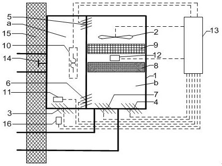
[0028] like figure 1As shown, an air purifier includes: an airtight cabin 1, a fan 2, a first electronically controlled air valve 3 to a fifth electrically controlled air valve 7, a coarse filter 8, high-efficiency renewable VOCs and formaldehyde adsorption materials 9, Heating element 10, VOCs sensor 11, first temperature sensor 12, second temperature sensor 16, control processor unit 13, pressure relief valve 14; described VOCs sensor 11, first temperature sensor 12 and second temperature sensor 16 are respectively connected with The input end of the control processor unit 13 is connected; the fan 2 , the heating element 10 , the first electronically controlled air valve 3 to the fifth electronically controlled air valve 7 are respectively connected with the output end of the control processor unit 13 .

[0029] The coarse-effect filter 8 and high-efficiency renewable VOCs and formaldehyde adsorption material 9 constitute an air purification module; the coarse-effect filter ...


PUM


Abstract

The invention discloses an air purifier and a realization method thereof. The purifier is a wall-mounted air purifier which is separated by a heat insulation plate connected with a controlled air duct at the upper and lower ends, and has an air purification room arranged on the left and right and a heating regeneration room installed with a heating element. The purifier is that the lower wall of the heating and regeneration chamber is provided with a controlled air passage connected with the indoor air, which is used for purifying air output and fresh air output, and replenishing air during sewage discharge; outside the air purifier, heating regeneration A second temperature sensor is installed at the inlet and outlet of the air duct on the lower wall of the room to monitor the room temperature and the output temperature of the purification and fresh air; the first temperature sensor is installed in the air purification room to monitor the temperature inside the purification module and the purifier, as well as indirectly monitor the room temperature and outdoor fresh air temperature. The method is that when blowing down the sewage, not only the waste gas in the heating and regeneration room and the dust adsorbed on the coarse-effect filter are brought out at one time, but also the heating element is turned off in a delayed manner, so that the sewage can be discharged more effectively, and the purification / fresh air output can be increased through the heating element. temperature.

Description

technical field [0001] The invention belongs to the technical field of indoor air purification, and in particular relates to a heat regeneration wall-mounted air cleaner in which a heating regeneration chamber and an air purification chamber are vertically arranged on the left and right, and there is only one common air duct for fresh air / sewage discharge to the outside, and a realization method thereof. Background technique [0002] In the prior art, for the thermal regeneration wall-mounted air purifier with the heating regeneration chamber and the air purification chamber being vertically arranged on the left and right, and there is only one fresh air / drainage public air duct to the outside, when it discharges the air purification chamber, it cannot be synchronized. The defect of taking the dust adsorbed on the air purification module and the heated and regenerated indoor dirty air out of the outdoor. For example, the patent application number is 201510898501.0, a wall-mo...

Claims


Application Information

Patent Timeline
Patent Type & Authority Patents(China)
IPC IPC(8): F24F8/108F24F7/08F24F7/003F24F13/28F24F11/89F24F11/65F24F11/61F24F11/80F24F110/10
CPCF24F7/08F24F13/28F24F11/61F24F11/65F24F11/80F24F11/89F24F2110/10F24F8/10F24F8/108
Inventor 何丰瀚
Owner 浙江尚品机电工程有限公司
Learn More