Fuel cell membrane electrode performance test method

A technology of fuel cell membrane and testing method, which is applied in the direction of measuring electricity, measuring devices, measuring electrical variables, etc., and can solve the problems of inability to evaluate performance, performance attenuation, etc.

Inactive Publication Date: 2020-05-05
浙江锋源氢能科技有限公司 +1
View PDF9 Cites 7 Cited by
  • Summary
  • Abstract
  • Description
  • Claims
  • Application Information

AI Technical Summary

Problems solved by technology

[0006] Therefore, the technical problem to be solved by the present invention is to overcome the defect that the performance of the fuel cell in the prior art will gradually decay when it is started and shut down, but it is impossible to evaluate its performance, thereby providing a fuel cell membrane electrode performance testing method

Method used


Image

  • Fuel cell membrane electrode performance test method
  • Fuel cell membrane electrode performance test method
  • Fuel cell membrane electrode performance test method

Examples


Embodiment 1

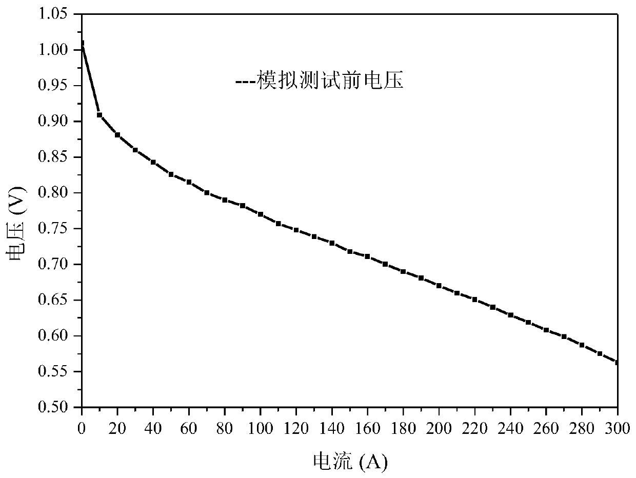
[0090] Example 1 Membrane electrode polarization curve test before simulating vehicle working conditions

[0091] Step 1: Assemble the fuel cell stack with the membrane electrode, bipolar plate and other accessories, install it on the test platform, connect the gas and cooling water pipes, and check the air tightness.

[0092] Step 2: Pass N2 through the cathode and anode of the battery stack to purge the battery stack.

[0093] Step 3: Set test conditions including temperature, humidity, flow, pressure test

[0094] Step 4: Activate the stack according to the selected test conditions.

[0095] Step 5: After the activation is completed, select the constant current mode for the test, the test current range is 0-300A, the test current point interval is 10A, and each load lasts for 1min. After the performance is stable, record the voltage value and power value, and test the stack membrane electrode Polarization curve performance.

Embodiment 2

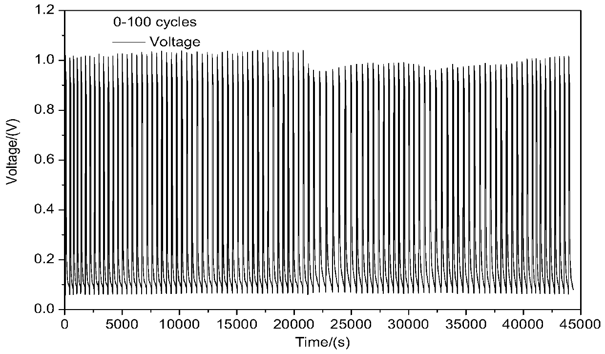
[0096] Embodiment 2 simulates the start-stop experimental test of vehicle operating conditions

[0097]Step 6: Carry out a simulated on-board working condition test. Test method: The air on the cathode side is normally open, the anode is first fed with H2 to raise the voltage of the single cell to OCV (open circuit voltage) and maintained for 1min, then the anode inlet H2 is closed, and the air is fed from the anode outlet to the cell. The hydrogen is purged, and the battery voltage drops to the lowest stable voltage for 1 minute, which is a complete start-stop cycle. After a start-stop cycle, close the air at the anode outlet, open the H2 at the inlet, and start a new start-stop cycle. Set to repeat the above test procedure test 100 times to complete the simulated vehicle working condition test.

[0098] Step 6 may also preferably include the following steps (step 6.1: feed N2 to the cathode and anode of the battery stack, and purging the battery stack.

[0099] Step 6.2: ...

Embodiment 3

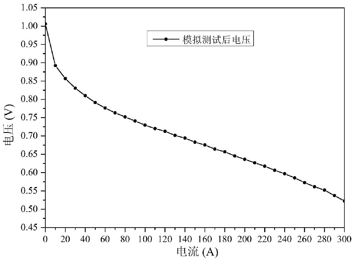
[0102] Example 3 After simulating the vehicle working conditions, the membrane electrode polarization curve test

[0103] Step 8: Start the test program, pass N2 to the cathode and anode of the battery stack, and purge the battery stack.

[0104] Step 9: Set test conditions including temperature, humidity, flow, pressure test

[0105] Step 10: Test the polarization curve of the membrane electrode after the simulated working condition. The test current range is 0-300A, the test current point interval is 10A, and each loading lasts for 1min. After the performance is stable, record the voltage value and power value, and test the stack Polarization curve performance of membrane electrodes.

[0106] Step 11: After simulating the vehicle working conditions, after the polarization curve test is completed, pass N2 to the cathode and anode of the battery stack to purge the battery stack.


PUM


Abstract

The invention provides a fuel cell membrane electrode performance test method which comprises the following steps: a performance test step before working condition simulation: testing a polarization performance curve of a cell stack membrane electrode; a simulated working condition test step: introducing air into the cathode side of the cell stack, introducing H2 into the anode of the cell stack for a preset time length, then closing an anode inlet H2, and introducing air from an anode outlet to purge the hydrogen in the single cell; a performance test step after working condition simulation:testing the polarization performance curve of the membrane electrode of the cell stack; and an evaluation step: comparing the polarization performance curve before the simulated working condition withthe polarization performance curve after the simulated working condition to obtain a performance change result and a durability evaluation result of the membrane electrode. The invention provides a simple, convenient and efficient test strategy for the performance of the membrane electrode of the proton exchange membrane fuel cell, the actual vehicle-mounted working condition is simulated, the performance change of the membrane electrode is evaluated by evaluating the polarization curve method before and after the test and then the durability of the membrane electrode is evaluated.

Description

technical field [0001] The invention belongs to the technical field of fuel cells, and in particular relates to a method for testing the performance of fuel cell membrane electrodes. Background technique [0002] Proton exchange membrane fuel cell (PEMFC) is a clean and environmentally friendly electrochemical power generation device, due to its small size, light weight, mild operating conditions, high energy conversion rate, simple structure and rapid response, etc. Ideal for portable power and transportation. Therefore, PEMFC is considered to be the preferred clean and efficient power generation device in the 21st century. In recent years, countries around the world are actively developing fuel cell electric vehicles with fuel cell stack modules as the main power source. [0003] The stability and durability of vehicle-mounted fuel cell stacks have always been important factors restricting its large-scale commercial application. There are many factors that affect the per...

Claims


Application Information

Patent Timeline
IPC IPC(8): G01R31/378G01R31/382
CPCG01R31/378G01R31/382
Inventor 冯翌袁蕴超沈润祝传贺王海峰王利生
Owner 浙江锋源氢能科技有限公司
Why Eureka
Try Eureka