Heat dissipation power distribution cabinet

A technology for power distribution cabinets and cooling pipes, applied in substation/power distribution device housings, electrical components, substation/switch layout details, etc., can solve problems such as difficult heat dissipation, potential safety hazards, and affecting the use of components, so as to facilitate heat dissipation The effect of treatment

Active Publication Date: 2020-05-05
ANHUI MINGYUAN POWER EQUIP MFR
View PDF12 Cites 4 Cited by
  • Summary
  • Abstract
  • Description
  • Claims
  • Application Information

AI Technical Summary

Problems solved by technology

[0003] However, the existing outdoor box-type power distribution cabinets usually have a structure with vents. Due to the long-term operation of the power distribution cabinet equipment, the problem inside the box is too high and it is difficult to dissipate heat, and the setting of the vents cannot solve the problem. These heat dissipation probl

Method used


Image

  • Heat dissipation power distribution cabinet
  • Heat dissipation power distribution cabinet
  • Heat dissipation power distribution cabinet

Examples


Embodiment Construction

[0018] In order to make the objectives, technical solutions, and advantages of the present invention clearer, the following further describes the present invention in detail in conjunction with specific embodiments and with reference to the accompanying drawings.

[0019] It should be noted that all the expressions "first" and "second" in the embodiments of the present invention are used to distinguish two entities with the same name but not the same or parameters that are not the same, as shown in "first" and "second" Only for the convenience of presentation, it should not be construed as a limitation to the embodiments of the present invention, and subsequent embodiments will not describe this one by one.

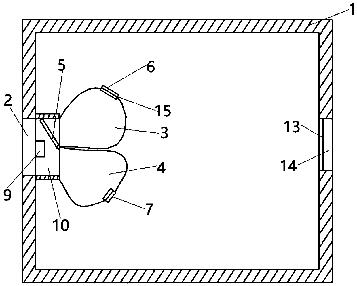
[0020] A heat-dissipating power distribution cabinet includes a cabinet body 1, an air outlet 14 is opened on the right side of the cabinet body 1, an air inlet 2 is opened on the left side of the cabinet body 1, and a heat dissipation pipe is connected to one side of the air i...


PUM


Abstract

The invention discloses a heat dissipation power distribution cabinet which comprises a cabinet body. An air outlet is formed in the right side of the cabinet body. An air inlet is formed in the leftside of the cabinet body. One side of the air inlet is communicated with a radiating pipe. The radiating pipe is arranged in cabinet body, and an air pump is arranged in the radiating pipe. A rotary switch is arranged in the middle of the other end of the radiating pipe. A first airbag is arranged on one side of the rotary switch. The first air bag communicates with radiating pipe. A first air outlet is formed in the first air bag. A first air outlet valve is arranged at the first air outlet. A first dust outlet is formed in the lower end of the first air bag. A first conductive screen is arranged at the first dust outlet. The first conductive screen is connected with an electrostatic generator and an electrostatic eliminator. The first air bag communicates with a dust accumulation chamberthrough the first dust outlet. According to the invention, heat dissipation processing is carried out on components in the cabinet body conveniently; and meanwhile, dust in air is effectively prevented from entering the cabinet body to influence the working process of the components.

Description

Technical field [0001] The invention relates to the technical field of power distribution cabinets, in particular to a heat dissipation power distribution cabinet. Background technique [0002] Power distribution cabinets are divided into power distribution cabinets, lighting distribution cabinets, and metering cabinets. They are the final equipment of the power distribution system. At the same time, the power distribution cabinet is also the collective name for the motor control center. The power distribution cabinet is used in the occasions where the load is relatively dispersed and there are few circuits, and the motor control center is used in the occasions where the load is concentrated and there are many circuits. They distribute the electric energy of a certain circuit of the upper-level power distribution equipment to the nearby load. This level of equipment should provide protection, monitoring and control of the load. [0003] However, the existing outdoor box-type powe...

Claims


Application Information

Patent Timeline
IPC IPC(8): H02B1/56H02B1/30H02B1/28
CPCH02B1/28H02B1/30H02B1/565
Inventor 吴桢戴俊镭
Owner ANHUI MINGYUAN POWER EQUIP MFR
Why Eureka
Try Eureka