Automatic poultry feeder

An automatic feeding and poultry technology, applied in the field of poultry farming, can solve the problems of feeding manpower consumption, etc., and achieve the effect of saving manpower, effective feeding, and good feeding

Inactive Publication Date: 2020-05-08
徐若琛
View PDF7 Cites 0 Cited by
  • Summary
  • Abstract
  • Description
  • Claims
  • Application Information

AI Technical Summary

Problems solved by technology

[0004] The purpose of the present invention is to solve the serious problem of feeding manpower consumption in the prior art, and a kind of poultry automatic feeder proposed

Method used


Image

  • Automatic poultry feeder
  • Automatic poultry feeder
  • Automatic poultry feeder

Examples


Embodiment 1

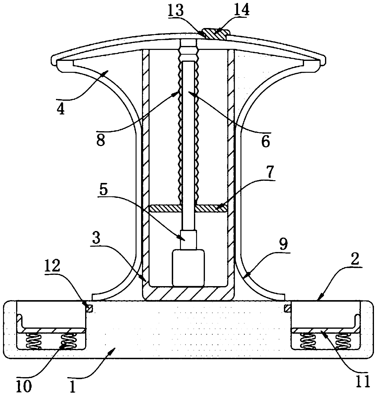
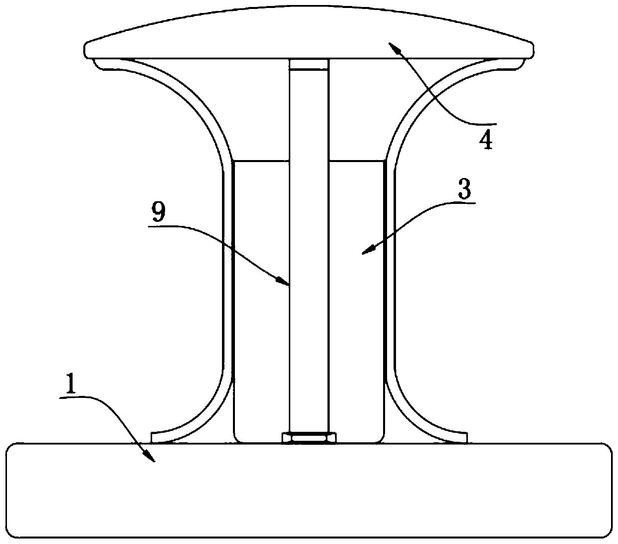
[0019] refer to Figure 1-2 , a poultry automatic feeder, comprising a base 1, the upper end of the base 1 is provided with an annular trough 2, the upper end of the base 1 is fixed with a storage box 3, the side wall of the storage box 3 is fixed with a top cover 4, the top cover The bottom of 4 is a slope, and the feed that enters from the upper end of the storage box 3 will roll along the bottom slope of the loam cake 4. The inner bottom of the storage box 3 is fixed with a motor 5, and the output shaft of the motor 5 is fixed with a screw rod 6. The circumferential side wall of the rod 6 is threadedly connected with a square push plate 7, and the screw mandrel has 6 reciprocating screw rods, which can automatically return after the push plate 7 has moved to the maximum position, which is convenient for repeated feeding. The inner top of the cover 4 is jointly fixed with a shrink film 8, the shrink film 8 is made of an elastic material, which can expand and contract and pre...

Embodiment 2

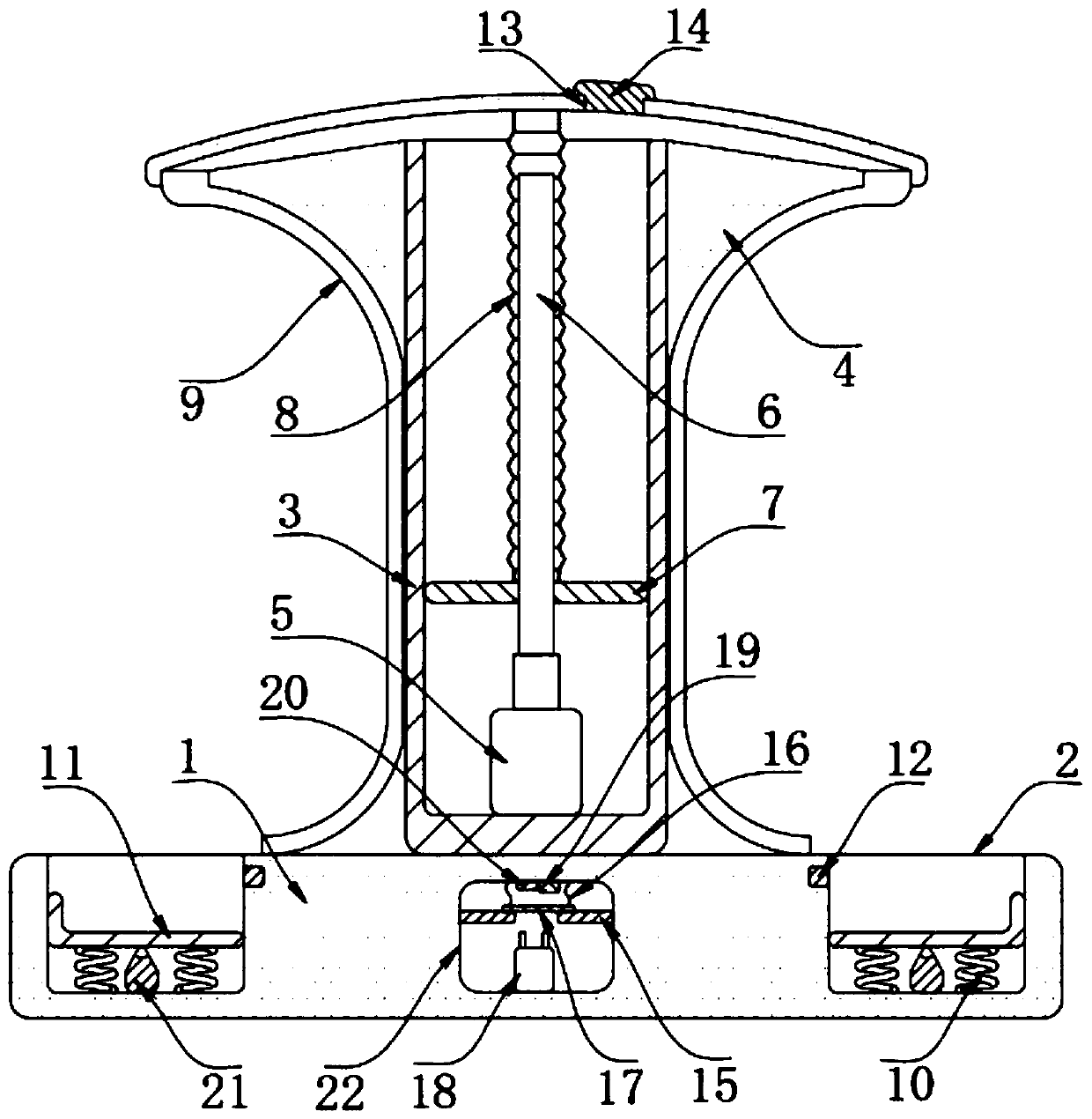
[0024] refer to Figure 1-3 The difference between this embodiment and Embodiment 1 is that a control cavity 22 is provided inside the base 1, two symmetrically arranged power plates 15 are fixed on the inner wall of the control cavity 22, and an inductor 18 is fixed on the bottom of the control cavity 22. The upper end of cavity 22 is fixed with electromagnet 19, delay magnet 20 and connecting spring 16, and delay magnet 20 is electromagnet, and the lower end of connecting spring 16 is fixed with connecting plate 17, and connecting plate 17 is permanent magnet, and connecting plate 17, two An electric connection plate 15, a photoresistor 12 and a motor 5 form a closed loop with an external power supply. The bottom of the food tank 2 is fixed with an electric shock block 21, and the bottom of the carrier plate 11 is fixed with a conductive sheet, and the electric shock block 21, conductive sheet, and inductor 18 And the delay magnet 20 forms a closed electric circuit with the ...


PUM


Abstract

The invention discloses an automatic poultry feeder which comprises a base, an annular feeding trough is formed in the upper end of the base, a storage box is fixed to the upper end of the base, an upper cover is fixed to the side wall of the storage box, a motor is fixed to the inner bottom of the storage box, and a lead screw is fixed to an output shaft of the motor. And the circumferential sidewall of the lead screw is in threaded connection with a square push plate, a shrink film is jointly fixed to the upper end of the push plate and the inner top of the upper cover, and a feeding opening is formed in the top of the upper cover in a penetrating mode. The feeding device has the advantages that the motor drives the lead screw to rotate, so that the push plate upwards pushes feed out ofthe storage box, the feed rolls into the discharging pipe along the bottom of the upper cover and enters the feeding trough along the discharging pipe, and the feed collides with the edge of the bearing plate to be distributed under the influence of the gravitational acceleration in the falling process; the feed spreading is realized, and the better feeding can be realized.

Description

technical field [0001] The invention relates to the technical field of poultry breeding, in particular to an automatic poultry feeder. Background technique [0002] With the continuous improvement of people's living standards, people's demand for meat food has increased, and the intensive breeding of poultry has been greatly developed. Through short-cycle feeding, effective meat supply can be achieved, thereby meeting market demand. The poultry farming industry has developed rapidly. [0003] Raising poultry inevitably requires feeding poultry. Due to the large number of poultry raised in the same batch, in order to ensure the effective growth of poultry, it is necessary to feed them in a timely manner, and then it is necessary to spread the feed multiple times to ensure the quality of feeding. During the period, it is also necessary to control the number of feedings, not to feed blindly, and to monitor the feeding effect in time, which makes the breeders spend more labor o...

Claims


Application Information

Patent Timeline
Patent Type & Authority Applications(China)
IPC IPC(8): A01K39/012A01K39/014
CPCA01K39/0125A01K39/014
Inventor 徐若琛李沛泽
Owner 徐若琛
Why Eureka
Try Eureka