Detachable sun umbrella
A sun umbrella, detachable technology, applied in walking sticks, travel goods, applications, etc., can solve the problem of occupying space, and achieve the effect of safe occupying space, not easy to deform, and stable structure
- Summary
- Abstract
- Description
- Claims
- Application Information
AI Technical Summary
Problems solved by technology
Method used
Image
Examples
Embodiment 1
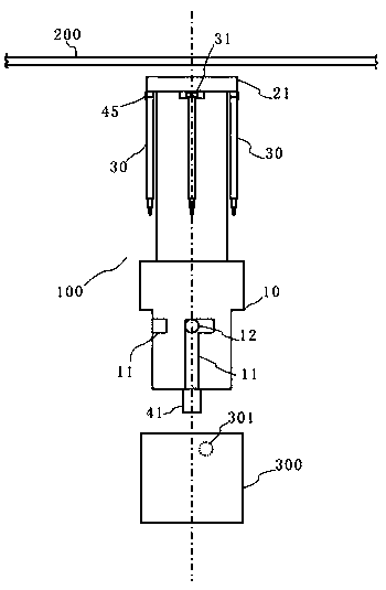
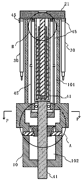
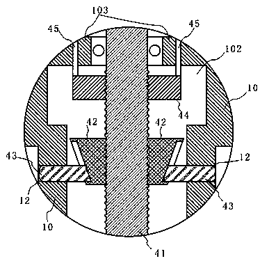
[0031] Such as Figure 1-8 11, the present embodiment provides a detachable sun umbrella, including an umbrella frame 100, a handle 300 and an umbrella surface 200, the umbrella frame 100 includes a control cylinder 10 with an upper open cavity, a telescopic middle rod 20 and several telescopic umbrella ribs 30, the bottom of the telescopic middle rod 20 is located in the inner cavity of the control cylinder 10 and the top of the telescopic middle rod 20 has a sealing plate 21 located outside the control cylinder 10, and the circumferential direction of the several telescopic umbrella ribs 30 is uniform. cloth and are respectively movably connected to the sealing plate 21 on the top of the telescopic middle rod 20 through hinges, the handle 300 is detachably installed on the bottom of the control cylinder 10, and the umbrella surface 200 is detachably installed on the sealing plate 21 and each telescopic umbrella At the end of the rib 30 , the inner cavity of the control cylin...
Embodiment 2
[0044] This embodiment 2 further makes the following improvements on the basis of the above-mentioned embodiment 1: as Figure 9 As shown, the pulling seat 44 is rotatably provided with a pull shaft 47 through a bearing, and one end of the pull rope 45 is fixedly connected to the pull shaft 47, and one end of the pull shaft 47 protrudes from the outer wall of the control cylinder 10, and the control The cylinder body 10 and the telescopic middle rod 20 are respectively provided with a chute for the pull shaft 47 to move up and down at the positions corresponding to the pull shaft 47. When the telescopic rib 30 is fully expanded and the pull seat 44 goes down to the lowest position, the pull rope 45 and the pull shaft 47 is exposed, and when the umbrella frame 100 is accommodated, the exposed pull shaft 47 end can be operated to wind the stay cord 45 on the pull shaft 47, and the pull shaft 47 is free to rotate at the same time, so the rod 20 in the expansion and contraction St...
Embodiment 3
[0046] The present embodiment 3 further makes the following improvements on the basis of the above-mentioned embodiment 1: as Figure 10 As shown, a pull shaft 47 is protrudingly provided on the pull seat 44, and one end of the stay rope 45 is fixedly connected to the pull shaft 47 through a scroll spring 48. The scroll spring 48 is the tightest at the lowest point, and the action of the scroll spring 48 can automatically shorten the pull cord 45 and hide it in the control cylinder 10 when the telescopic middle rod 20 is restored, and pull the telescopic middle rod 20 when it is elongated. The cord 45 is also pulled out.
PUM
 Abstract
Description
Claims
Application Information
 - R&D
- Intellectual Property
- Life Sciences
- Materials
- Tech Scout
- Unparalleled Data Quality
- Higher Quality Content
- 60% Fewer Hallucinations
Browse by: Latest US Patents, China's latest patents, Technical Efficacy Thesaurus, Application Domain, Technology Topic, Popular Technical Reports.
© 2025 PatSnap. All rights reserved.Legal|Privacy policy|Modern Slavery Act Transparency Statement|Sitemap|About US| Contact US: help@patsnap.com


