An active-passive hybrid drive intelligent prosthetic knee joint structure

A technology of hybrid drive and intelligent prosthetics, applied in prosthesis, medical science, artificial legs, etc., can solve problems such as difficult production capacity, unreliable stability of pneumatic knee joint support performance, safety accidents, etc.

Active Publication Date: 2022-03-25
UNIV OF SHANGHAI FOR SCI & TECH
View PDF14 Cites 1 Cited by
  • Summary
  • Abstract
  • Description
  • Claims
  • Application Information

AI Technical Summary

Problems solved by technology

The magnetorheological smart knee joint adjusts the damping effect by changing the current to change the magnetic field strength, but the viscosity change of the magnetorheological fluid is closely related to the magnetic field, and it has high requirements on the material of the magnetorheological fluid, which is not easy to control and is not easy Increase production capacity
Both hydraulic pressure and air pressure use a microprocessor to drive the motor to adjust the opening of the valve inside the damping cylinder, so as to achieve the purpose of adjusting the damping. However, the stability of the pneumatic knee joint support performance is unreliable, which is likely to cause safety accidents
[0003] Patent No. US201100873391A1, Patent No. 105769395A, Patent No. 106726028B, Patent No. 106539633A and Patent No. 107035808A all propose electronically controlled hydraulic damping cylinder structures for intelligent knee joint prostheses, but they are all pure damping types in nature and cannot be used when going up stairs. , Provide active torque when going uphill

Method used


Image

  • An active-passive hybrid drive intelligent prosthetic knee joint structure
  • An active-passive hybrid drive intelligent prosthetic knee joint structure
  • An active-passive hybrid drive intelligent prosthetic knee joint structure

Examples


Embodiment Construction

[0020] In order to make the technical means, creative features, achieved goals and effects of the present invention easy to understand and understand, the present invention is described in detail below with reference to the embodiments and the accompanying drawings.

[0021]

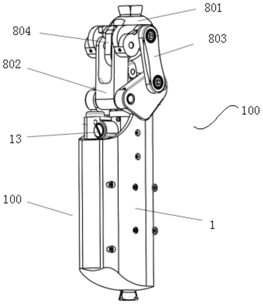
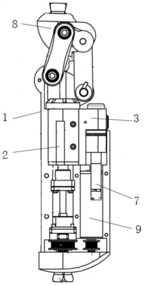
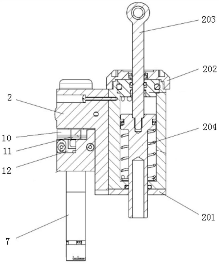
[0022] figure 1 It is a perspective view of a knee joint structure of an active-passive hybrid drive intelligent prosthetic limb in an embodiment of the present invention. figure 2 This is a schematic diagram of the internal structure of an active-passive hybrid drive intelligent prosthetic knee joint structure in an embodiment of the present invention. image 3 It is a schematic diagram of a bidirectional damping cylinder in an embodiment of the present invention. Figure 4 It is a schematic diagram of the driving mechanism in the embodiment of the present invention. Figure 5 It is a schematic diagram of the two-way damping cylinder and the damping adjustment seat in the embodiment of the present ...


PUM


Abstract

The invention relates to the field of wheelchairs, and discloses an active-passive hybrid driving intelligent prosthetic knee joint structure, which is used to provide users with required damping and power assistance. An active-passive hybrid driving intelligent prosthetic knee joint structure of the present invention includes: a prosthetic body; a controller installed in the prosthetic body; a two-way damping cylinder, the two-way damping cylinder has a first chamber and a second chamber separated from each other by a push rod ; The damping adjustment seat has an extension hydraulic passage and a buckling hydraulic passage respectively communicated with the first chamber and the second chamber; the first one-way valve is installed in the extension hydraulic passage, and the second one-way valve is installed in the buckling hydraulic passage; The damping regulating valve is used to change the flow direction of the hydraulic oil; the DC servo motor is used to drive the damping regulating valve to rotate; the four-bar linkage mechanism is located on the top of the prosthesis body to realize the user's squat; the driving mechanism is installed on the prosthesis body and electrically connected to the controller.

Description

technical field [0001] Embodiments of the present invention relate to the field of wheelchairs, and in particular, to an active-passive hybrid drive intelligent prosthetic knee joint structure. Background technique [0002] With the increase of lower limb amputees and the continuous development of microelectronics, control and other technologies, intelligent lower limb prosthesis has gradually become a research hotspot in the field of rehabilitation robots. As the core component of the lower limb prosthesis system, high-performance knee joint prosthesis design is still the main technical difficulty in the current prosthetic limb design. At present, the existing intelligent prosthetic knee joints can be divided into passive type and active type according to the joint driving mode. The passive prosthetic knee joint adjusts the damping torque of the knee joint according to changes in external conditions to achieve gait adjustment, but because it does not provide active torque,...

Claims


Application Information

Patent Timeline
Patent Type & Authority Patents(China)
IPC IPC(8): A61F2/64A61F2/70A61F2/74
CPCA61F2/64A61F2/68A61F2002/701A61F2/748A61F2/74
Inventor 郑宏宇汪晓铭喻洪流孟巧玲张哲文孙金悦杨洁李科静蓝贺
Owner UNIV OF SHANGHAI FOR SCI & TECH
Why Eureka
Try Eureka