Eureka AIR delivers breakthrough ideas for toughest innovation challenges, trusted by R&D personnel around the world.

Transitional bracket device

A technology for transition brackets and roofs, which is applied in the direction of pillars/brackets, temporary shields, mining equipment, etc.

Inactive Publication Date: 2020-05-08
BAOJI PETROLEUM MASCH CO LTD +2
View PDF6 Cites 0 Cited by
  • Summary
  • Abstract
  • Description
  • Claims
  • Application Information

AI Technical Summary

Problems solved by technology

[0003] The invention provides a transition support device, which solves the current situation that the pipe string is manually moved between the pipe bent frame and the power catwalk during the workover operation, and realizes the automatic discharge of the pipe string

Method used


Image

  • Transitional bracket device
  • Transitional bracket device
  • Transitional bracket device

Examples


Embodiment Construction

[0024] The present invention will be described in detail below in conjunction with the accompanying drawings and specific embodiments.

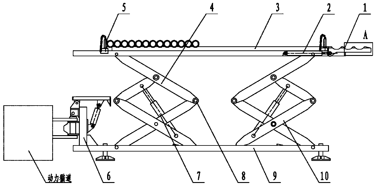
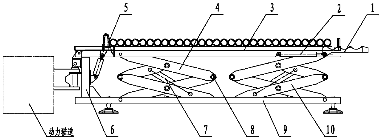
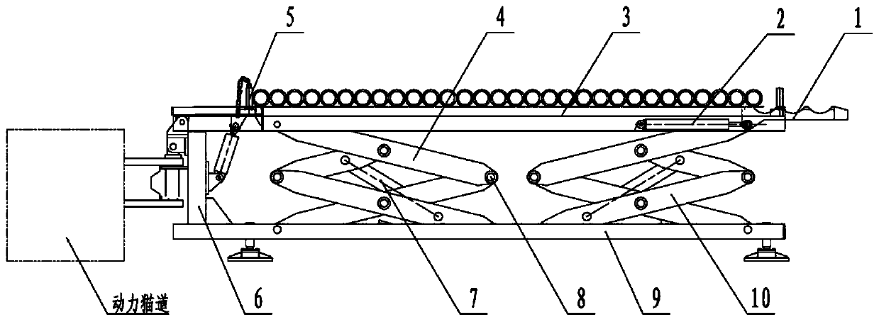
[0025] The technical solution adopted in the present invention is a transition bracket device, such as figure 1 As shown, a base 9 is included, a top plate 3 is arranged above the base 9, a first telescopic assembly 4 and a second telescopic assembly 10 arranged side by side are installed between the top plate 3 and the base 9, and the top plate 3 is close to one end of the second telescopic assembly 10 A pipe hooking mechanism 1 is installed, and the top plate 3 is provided with a pipe unloading mechanism 6 at the opposite end of the pipe hooking mechanism 1 , and the pipe unloading mechanism is installed on the base 9 .

[0026] Such as Figure 1-3 As shown, the first telescopic assembly 4 and the second telescopic assembly 10 are both scissor-fork structures, the scissor-fork mechanisms are hinged by pins 8, and a lifting cylinder 7 is in...


PUM


Abstract

The invention discloses a transitional bracket device which comprises a base, wherein a top plate is distributed above the base; a first telescopic component and a second telescopic component are mounted between the top plate and the base side by side; a pipe hooking mechanism is mounted at the end, close to the second telescopic component, of the top plate; a pipe dismantling mechanism is arranged at the end, opposite to the pipe hooking mechanism, of the top plate; and the pipe dismantling mechanism is mounted on the base. The transitional bracket device has the advantages of being simple instructure, reliable in performance, low in manufacturing cost and wide in applicable range, changes the current situation that during workover operation, a tubular column needs to be manually transferred between a pipe rack and a power catwalk for operation, realizes automatic arrangement of the tubular column during workover operation, lowers the labor intensity, improves the safety and finallyrealizes the purpose of reducing the staff.

Description

technical field [0001] The invention belongs to the technical field of petroleum machinery and equipment, and relates to a transition support device. Background technique [0002] At present, when the pipe string is moved from the pipe rack to the power catwalk by manual pulling during the workover operation, it is necessary to increase the height of the existing pipe rack in the oil field, which increases the operating cost of the oil field; It can only discharge single-layer pipe strings, and cannot adapt to the working conditions of placing multi-layer pipe strings on the pipe rack during operation; the power catwalk needs to manually push the pipe strings to the power catwalk pipe rack during operation, and cannot Realize the automatic discharge of the pipe string. It has the disadvantages of large number of operators, high labor intensity, low operation efficiency and low safety factor. Contents of the invention [0003] The invention provides a transition support d...

Claims


Application Information

Patent Timeline
Patent Type & Authority Applications(China)
IPC IPC(8): E21D15/44E21D15/60E21D15/55E21D19/00
CPCE21D15/44E21D15/55E21D15/60E21D19/00
Inventor 邢大伟张志伟刘延明张强王翠
Owner BAOJI PETROLEUM MASCH CO LTD
Why Eureka
Eureka Blog
Learn More