
Rendering method of light field camera 2.0 and electronic equipment

A light field camera and light field image technology, applied in image data processing, instruments, computing, etc., can solve problems such as large block effect and poor imaging effect, and achieve the goal of reducing block effect, improving imaging quality, and achieving high-precision rendering. Effect

Active Publication Date: 2020-05-08
SHENZHEN GRADUATE SCHOOL TSINGHUA UNIV
View PDF4 Cites 0 Cited by
  • Summary
  • Abstract
  • Description
  • Claims
  • Application Information

AI Technical Summary

Problems solved by technology

[0003] The usual light field camera 2.0 rendering method only uses the structural characteristics of the microlens to extract the corresponding microlens image blocks for splicing, which often causes a large block effect, which makes the final imaging effect poor. Can meet people's demand for light field data

Method used


Image

  • Rendering method of light field camera 2.0 and electronic equipment
  • Rendering method of light field camera 2.0 and electronic equipment
  • Rendering method of light field camera 2.0 and electronic equipment

Examples


Embodiment Construction

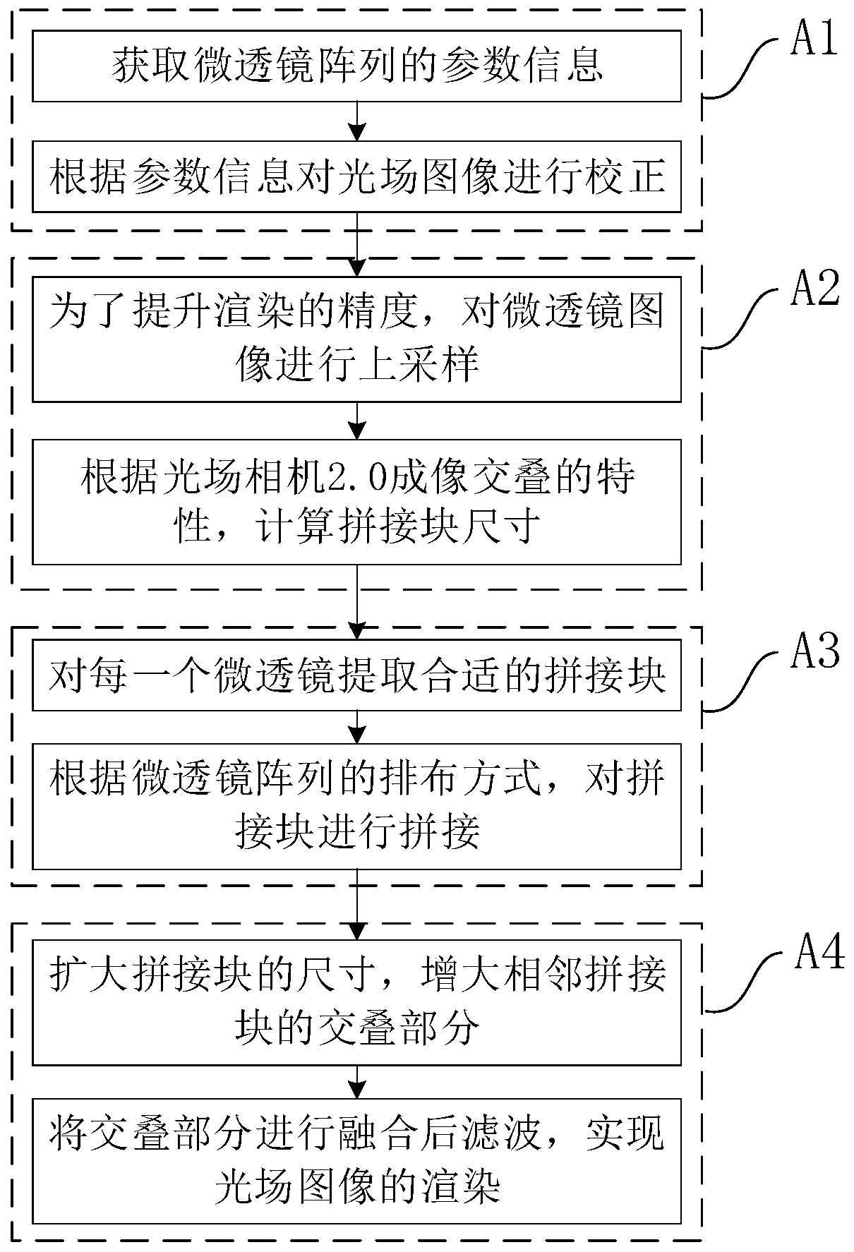
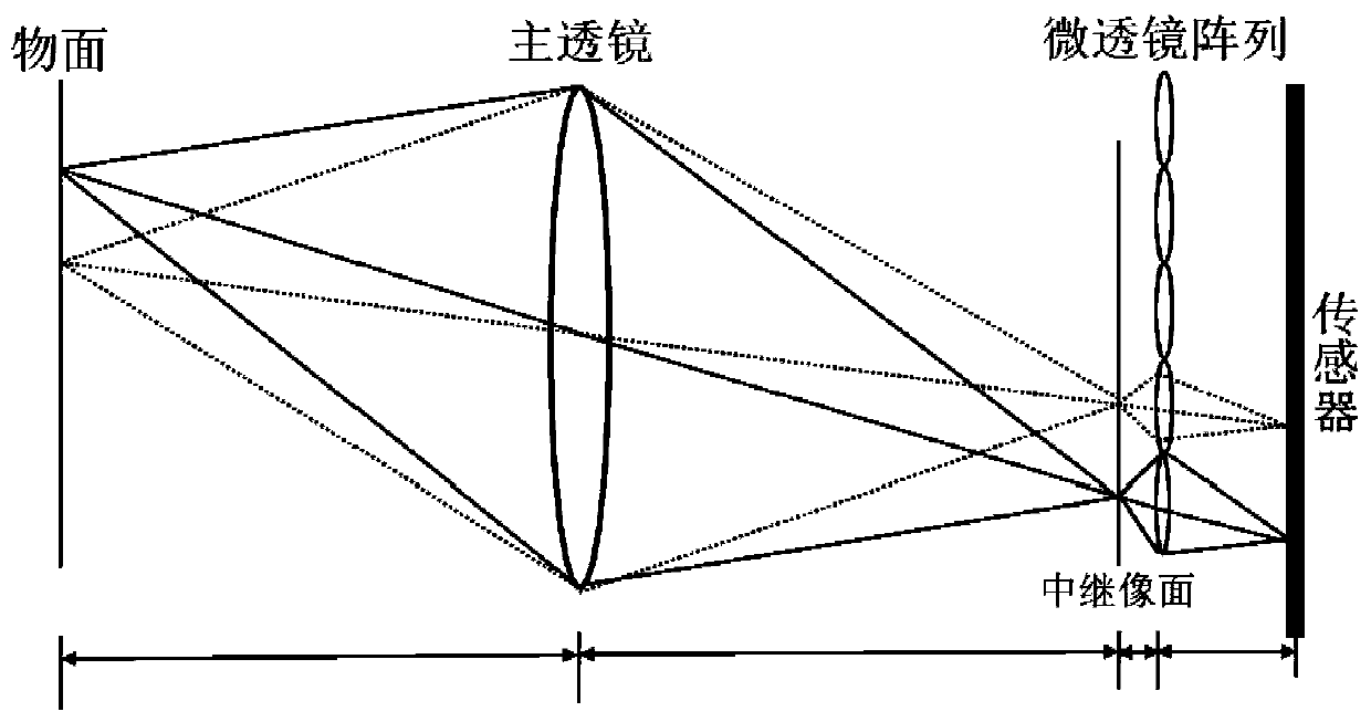
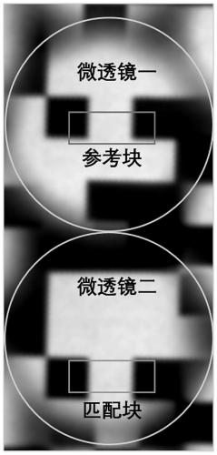
[0021] In order to make the technical problems, technical solutions and beneficial effects to be solved by the embodiments of the present invention clearer, the following combination Figure 1 to Figure 3 And embodiment, the present invention is described in further detail. In a specific embodiment, it can be operated in the following manner. It should be noted that the structure of the light field camera and the parameters of the microlens array in the following implementation process are just examples, and the scope of the present invention is not limited to the methods listed.

[0022] It is to be understood that the terms "length", "width", "top", "bottom", "front", "rear", "left", "right", "vertical", "horizontal", "top" , "bottom", "inner", "outer" and other indicated orientations or positional relationships are based on the orientations or positional relationships shown in the drawings, and are only for the convenience of describing the embodiments of the present inven...


PUM


Abstract

The embodiment of the invention discloses a rendering method of a light field camera 2.0 and electronic equipment. The method comprises the following steps that: A1, light field images are corrected based on the parameter information of a micro-lens array, so that the micro-lens images can be regularly placed; A2, the size of a splicing block corresponding to each micro-lens image is obtained according to the imaging characteristics of the light field camera 2.0; A3, micro-lens image blocks are extracted from each micro-lens image according to the sizes of the corresponding splicing blocks, and the micro-lens image blocks are spliced according to the geometric arrangement mode of the micro-lens array; and A4, the sizes of the micro-lens image blocks are expanded, so that the adjacent micro-lens image blocks can have overlapping parts, and the overlapping parts are fused, and filtering is performed, so that the rendering of the light field images can be realized. The processor of the electronic equipment may perform the method. With the rendering method of the embodiment of the invention adopted, the high-precision rendering of the images of the light field camera 2.0 can be realized, and the imaging quality of a rendering result can be improved.

Description

technical field [0001] The invention relates to the technical field of computer vision and digital image processing, in particular to a high-precision rendering method of a light field camera 2.0. Background technique [0002] Light Field Camera 2.0 is the second generation of light field cameras. The biggest difference between a light field camera and a traditional camera is that a microlens array is added to its structure, so that more effective information can be recorded on the sensor, including the direction information and position information of the scene. It is precisely because of this structure that the light field camera has many special capabilities, such as refocusing after taking a picture, changing the viewing angle, and obtaining depth information. Because the light field camera can capture the position and direction information of light at the same time, it has attracted extensive attention in virtual reality, holographic technology, 3D reconstruction and o...

Claims


Application Information

Patent Timeline
Patent Type & Authority Applications(China)
IPC IPC(8): G06T5/50
CPCG06T5/50G06T2207/20221
Inventor 金欣孙绪福戴琼海
Owner SHENZHEN GRADUATE SCHOOL TSINGHUA UNIV
Learn More