Fixing device for installing battery of new energy automobile

A technology for new energy vehicles and fixtures, applied in the direction of batteries, battery pack components, circuits, etc., can solve the problems of rising maintenance costs, battery pack damage, and cumbersome operations, and achieve easy installation and maintenance, easy installation, and easy installation. Effect

Inactive Publication Date: 2020-05-08
张和平
View PDF0 Cites 9 Cited by
  • Summary
  • Abstract
  • Description
  • Claims
  • Application Information

AI Technical Summary

Problems solved by technology

The existing technology has the disadvantages of cumbersome operation and high production cost when fixing the new energy vehicle battery, and the battery has no cushioning effect after being fixed, and the battery pack is easily damaged after being hit, which increases the subsequent maintenance cost; therefore, there are Necessary to improve existing technology

Method used


Image

  • Fixing device for installing battery of new energy automobile
  • Fixing device for installing battery of new energy automobile
  • Fixing device for installing battery of new energy automobile

Examples


Embodiment 1

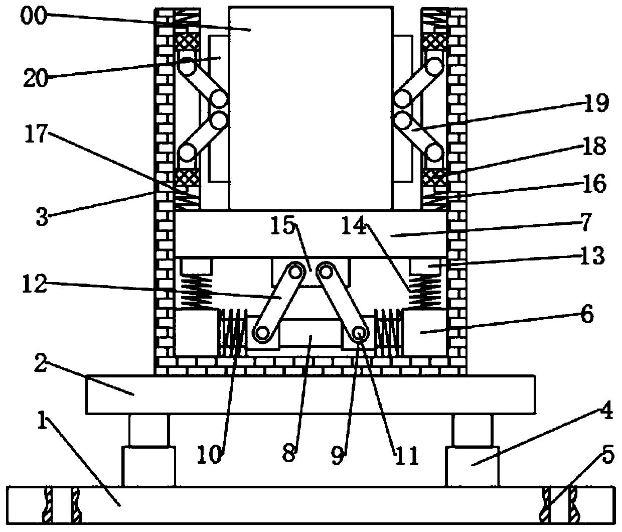
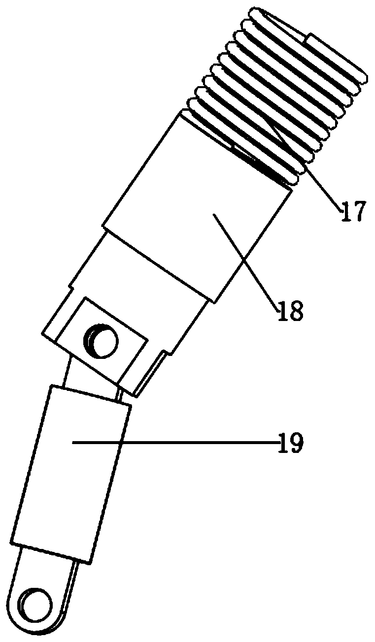
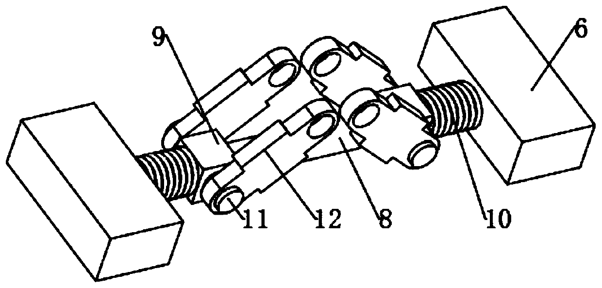
[0021] see Figure 1-5 , a new energy vehicle battery installation and fixing device, including a base 2, a cavity 3 is fixedly connected to the center of the upper end surface of the base 2, the inner cavity of the cavity 3 is hollow, a battery pack 00 is placed in the cavity 3, and the cavity 3 The left and right sides of the inner wall of the inner wall are provided with clamping structures, and the clamping structure includes a clamping groove 16, which is equidistantly arranged on the inside of the cavity 3, and the clamping groove 16 communicates with the inner cavity of the cavity 3, and the clamping groove 16 A corresponding snap-in block 18 is installed in the slot 16, and a snap-in spring 17 is fixedly connected between the snap-in slot 16 and the snap-in block 18. 18 is fixedly connected, and one end of the clamping block 18 away from the clamping spring 17 is rotatably connected with a clamping rod 19, the clamping rod 19 is arranged obliquely, and the end of the c...

Embodiment 2

[0030] In Embodiment 1, the battery pack 00 is fixed by the limit blocks 20 on the left and right sides inside the cavity 3. When the cavity 3 is subjected to a vertical impact, it may cause the battery pack 00 to collide with the front and rear sides inside the cavity 3. The impact damages the battery pack 00 and the cavity 3; therefore, this embodiment is improved on the basis of embodiment 1, and the improvement is: the limit plate 21 is movably connected to the front and rear sides of the cavity 3, and the limit plate 21 The quantity is two, the limiting plate 21 is fixedly connected with the inner side of the cavity 3 with a plurality of limiting springs 22, the limiting springs 22 are arranged equidistantly along the horizontal direction, and the contact surface between the limiting plate 21 and the battery pack 00 is provided with a protective layer to avoid scratching the surface of the battery pack 00.


PUM


Abstract

The invention discloses a fixing device for installing a battery of a new energy automobile, and the device comprises a base, wherein a cavity is fixedly connected to the upper end face of the base, abattery pack is placed in the cavity, and clamping structures are distributed on the left side and the right side of the inner wall of the cavity. The device is convenient to mount, and only a battery pack needs to be placed in the cavity with the proper size; limiting blocks and limiting plates are arranged on the periphery of the battery pack and connected with clamping springs and limiting springs correspondingly, so an impact force on the periphery of the cavity can be absorbed while the battery pack is fixed. A damping mechanism, vertical springs and transverse springs are arranged belowthe battery pack, so the vibration impact of the battery pack in the vertical direction can be reduced, and the battery pack is protected in all directions; besides, threaded holes are formed in thefour corner areas of the base, so the installation is convenient, the position of the base can be adjusted through the lifting air cylinder, and the battery pack can be installed and maintained conveniently.

Description

technical field [0001] The invention relates to the technical field of new energy vehicles, in particular to a new energy vehicle battery installation and fixing device. Background technique [0002] New energy vehicles refer to vehicles that use unconventional vehicle fuels as power sources, integrate advanced technologies in vehicle power control and drive, and form vehicles with advanced technical principles, new technologies, and new structures; therefore, new energy vehicle batteries are used in The interior of the entire car plays an integral role and is the most important car component. The existing technology has the disadvantages of cumbersome operation and high production cost when fixing the new energy vehicle battery, and the battery has no cushioning effect after being fixed, and the battery pack is easily damaged after being hit, which increases the subsequent maintenance cost; therefore, there are It is necessary to propose improvements to the prior art. Co...

Claims


Application Information

Patent Timeline
IPC IPC(8): H01M2/10
CPCH01M2200/00H01M50/20Y02E60/10
Inventor 张和平
Owner 张和平
Why Eureka
Try Eureka