
Shock absorber and vehicle

A technology of shock absorbers and shock absorbing components, which is applied in the field of vehicles and can solve problems such as poor buffering capacity, tearing of the rubber main ring, and damage to the shock absorber, so as to improve the ability of buffering and vibration reduction, avoid direct contact, and improve reliability. sexual effect

Inactive Publication Date: 2020-05-12
WEICHAI POWER CO LTD
View PDF8 Cites 6 Cited by
  • Summary
  • Abstract
  • Description
  • Claims
  • Application Information

AI Technical Summary

Problems solved by technology

[0003] The shock absorbers used on vehicles in the prior art have the following two structures. The first type is that two shock absorbers are installed symmetrically in a complete set during installation, and the positioning metal sleeve is placed in the mounting hole of the passive end connection device, and the end faces are not Contact, during the bolt tightening process, when the connecting plate at the active end is compressed to the positioning metal sleeve, when the lower fixing plate contacts the positioning metal sleeve below, due to the large tightening torque, the positioning metal sleeve is separated from the rubber ring, causing The shock absorber is damaged and loses its due effect, and the rubber metal plate is in direct metal contact with the passive end connection plate. When encountering an impact, the cushioning capacity is poor; the second type, the shock absorber is composed of a rubber main ring and a secondary ring. The center of the main ring has a mandrel sleeve vulcanized integrally with it. Except for the mandrel, the outer ring is made of rubber. When installing, the main ring and the auxiliary ring are used together. The edge of the mounting hole of the passive end connecting plate will continuously cut the rubber. Use leads to tearing of the rubber main ring, affecting the performance of the shock absorber and the attendance of the car

Method used


Image

  • Shock absorber and vehicle
  • Shock absorber and vehicle
  • Shock absorber and vehicle

Examples


Embodiment Construction

[0040] Exemplary embodiments of the present disclosure will be described in more detail below with reference to the accompanying drawings. Although exemplary embodiments of the present disclosure are shown in the drawings, it should be understood that the present disclosure may be embodied in various forms and should not be limited by the embodiments set forth herein. Rather, these embodiments are provided for more thorough understanding of the present disclosure and to fully convey the scope of the present disclosure to those skilled in the art.

[0041] It should be understood that the terminology used herein is for the purpose of describing particular example embodiments only and is not intended to be limiting. As used herein, the singular forms "a", "an" and "the" may also be meant to include the plural forms unless the context clearly dictates otherwise. The terms "comprising", "comprising", "containing" and "having" are inclusive and thus indicate the presence of stated...


PUM


Abstract

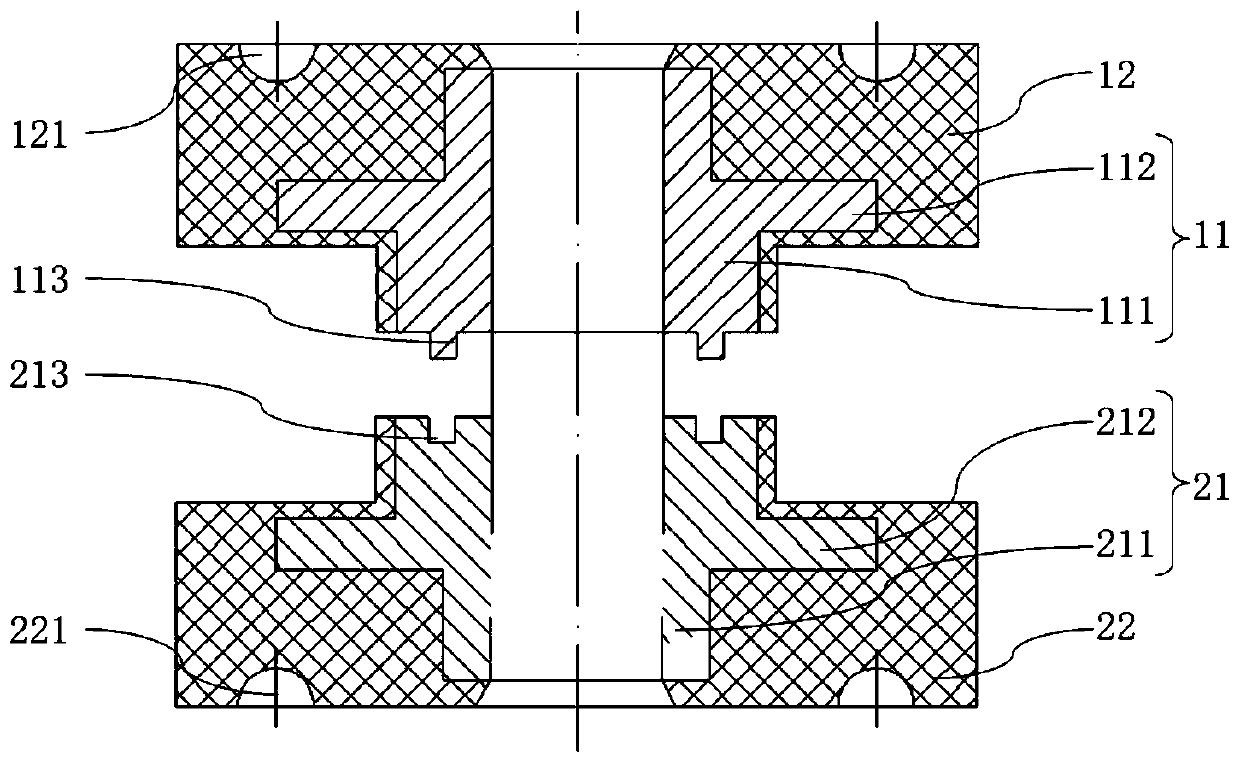
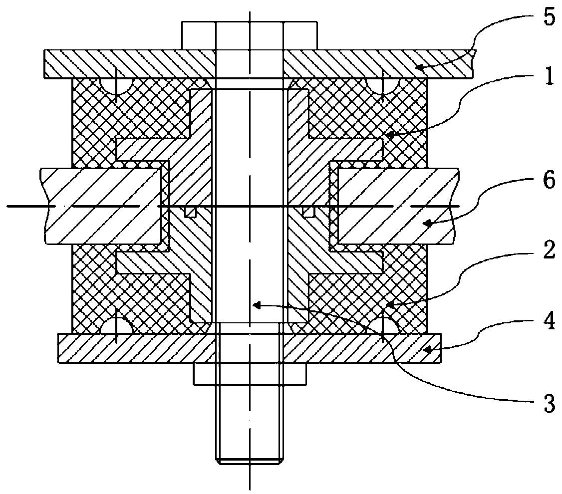
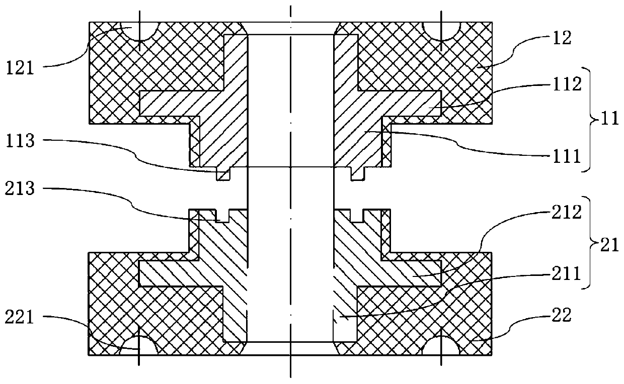
The invention belongs to the technical field of vehicles, and particularly relates to a shock absorber and a vehicle. The shock absorber comprises a connecting plate, a connecting bolt, a first shock-absorbing assembly and a second shock-absorbing assembly, wherein the first shock-absorbing assembly comprises a first sleeve and a first shock-absorbing part; the first shock-absorbing part covers afirst sleeve; the second shock-absorbing assembly comprises a second sleeve and a second shock-absorbing part; the second shock-absorbing part covers a second sleeve; and the connecting bolt sequentially passes through the first sleeve, the second sleeve and the connecting plate. According to the shock absorber of the embodiment, the first shock-absorbing part covers the first sleeve, and the second shock-absorbing part covers the second sleeve to avoid the problem that due effect is lost as a result of damages of the shocker absorber while a positioning metal sleeve is separated from a rubberring if tightening moment of force is relatively great.

Description

technical field [0001] The invention belongs to the technical field of vehicles, and in particular relates to a shock absorber and a vehicle. Background technique [0002] This section provides background information related to the present disclosure only and is not necessarily prior art. [0003] The shock absorbers used on vehicles in the prior art have the following two structures. The first type is that two shock absorbers are installed symmetrically in a complete set during installation, and the positioning metal sleeve is placed in the mounting hole of the passive end connection device, and the end faces are not Contact, during the bolt tightening process, when the connecting plate at the active end is compressed to the positioning metal sleeve, when the lower fixing plate contacts the positioning metal sleeve below, due to the large tightening torque, the positioning metal sleeve is separated from the rubber ring, causing The shock absorber is damaged and loses its d...

Claims


Application Information

Patent Timeline
IPC IPC(8): F16F1/373F16F1/38F16F15/08
CPCF16F1/373F16F1/3842F16F15/08
Inventor 田新伟徐止听胡亮
Owner WEICHAI POWER CO LTD
Features
  • Generate Ideas
  • Intellectual Property
  • Life Sciences
  • Materials
  • Tech Scout
  • Unparalleled Data Quality
  • Higher Quality Content
  • 60% Fewer Hallucinations
Learn More