Cascade type refrigerating and heating energy-saving system

An energy-saving system and cascading technology, which is applied in the field of heating and cooling energy saving, can solve the problems of low energy efficiency, narrow temperature environment range, large compressor load, etc., and achieve the goal of improving low-temperature heating performance, improving low-temperature adaptability, and stable system operation Effect

Inactive Publication Date: 2020-05-12
江苏辛普森新能源有限公司
View PDF4 Cites 1 Cited by
  • Summary
  • Abstract
  • Description
  • Claims
  • Application Information

AI Technical Summary

Problems solved by technology

[0002] The cooling and heating energy-saving system in the prior art cannot adapt to multi-working conditions, and cannot operate in low-temperature and harsh environments. When hot water above 50°C is produced below -20°C, the energy efficiency is low during operation, the compressor load is large, the life is short, the stability and reliability are poor, and the low temperature adaptability and low temperature heating performance cannot be improved, so it needs to be improved urgently.

Method used


Image

  • Cascade type refrigerating and heating energy-saving system
  • Cascade type refrigerating and heating energy-saving system
  • Cascade type refrigerating and heating energy-saving system

Examples


Embodiment 1

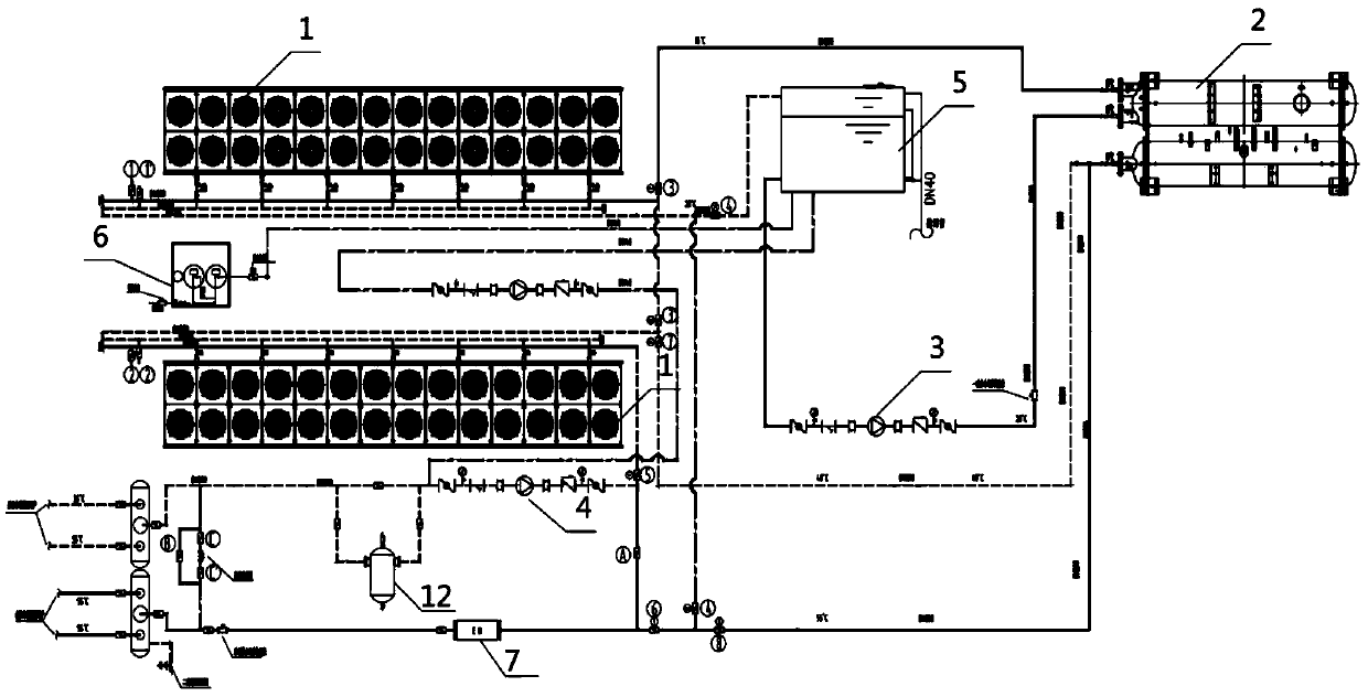
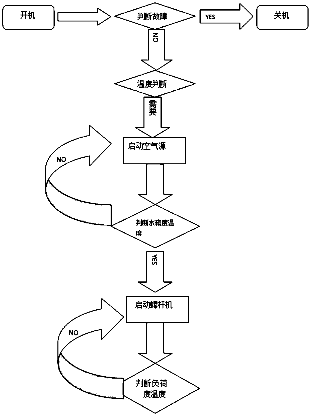
[0015] Such as figure 1 with image 3 As shown, this embodiment discloses a cascade cooling and heating energy-saving system, which includes two sets of air source modules 1, a screw heat source unit 2, a screw heat source unit water supply pump 3, an air conditioning system circulating pump 4, and a thermal buffer water tank 5. Complete water softener 6 and heating remote transmission summary table 7.

[0016] Among them, seven air source modules are responsible for producing 20℃ low-temperature water for the evaporative side heat source of screw heat source unit 2, and the other seven air source modules are installed on the return water side of the terminal system to conduct water supply to the condenser of screw heat source unit 2 When heated to 40°C, one screw heat source unit 2 is provided in this embodiment, and the condenser outlet water temperature of the screw heat source unit 2 is 55°C, and the return water temperature is 35°C.

[0017] In this embodiment, the capacity e...

Embodiment 2

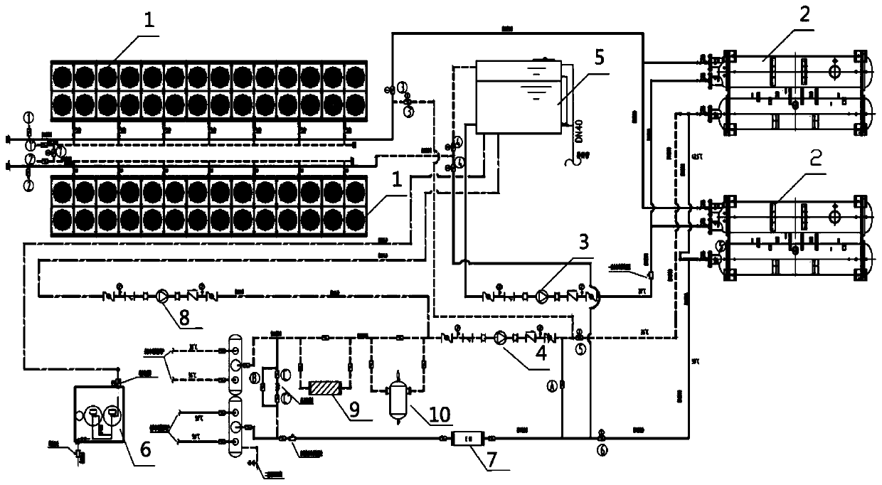
[0020] Such as figure 2 with image 3 As shown, the cascade cooling and heating energy-saving system in this implementation includes two sets of air source modules composed of several air source heat pumps 1, two screw heat source units 2, screw heat source unit water supply pumps 3, air conditioning system circulating pumps 4. Thermal buffer water tank 5, full-process water softener 6, heating remote transmission summary table 7, air source module heat storage circulation pump 8, coarse filter 9, and micro-bubble exhaust decontamination device 10; Two sets of air source modules 1 and two screw heat source units 2 are set correspondingly.

[0021] This implementation uses air as the heat source and water as the heat carrier during heating operation, and circulates through the thermal buffer water tank 5, screw heat source unit water supply pump 3, two screw heat source units 2, air source module 1, and connected pipelines. When the air source module 1 is working, the heat energ...


PUM


Abstract

The invention discloses a cascade type refrigerating and heating energy-saving system comprising two air source modules, at least one screw heat source unit, a screw heat source unit water supply pump, an air conditioning system circulating pump, a thermal energy buffer water tank, a heat supply remote transmission main meter and a microbubble exhaust dirt separator. Water ways of the two air source modules are arranged in a series connection manner and are both connected with the thermal energy buffer water tank, and generated thermal energy can be transferred to the thermal energy buffer water tank. The cascade type air source / water source heat pump heating system can operate in multiple working condition modes especially low-temperature severe environments, system operation is stable, and energy efficiency is high. The heating system can efficiently operate under wider temperature environment intervals, and switching of various operation modes can be achieved.

Description

Technical field [0001] The invention relates to the technical field of cooling and heating energy saving, in particular to a cascade cooling and heating energy saving system. Background technique [0002] The cooling and heating energy-saving system of the prior art cannot adapt to multiple operating conditions, and cannot operate in a harsh environment with low temperatures. Its operating temperature environment range is relatively narrow. The operating mode cannot be switched in an ultra-low temperature environment below -20°C. When high temperature hot water above 50℃ is generated below -20℃, the energy efficiency is low during operation, the compressor load is large, the life is short, the stability and reliability are poor, and the low temperature adaptability and low temperature heating performance cannot be improved, so it is urgent to improve. Summary of the invention [0003] Aiming at the deficiencies in the prior art, the present invention designs a cascade cooling and ...

Claims


Application Information

Patent Timeline
Patent Type & Authority Applications(China)
IPC IPC(8): F25B7/00F25B41/00F25B43/00F25B41/40
CPCF25B7/00F25B41/00F25B43/003F25B43/00F25B2500/31
Inventor 田磊
Owner 江苏辛普森新能源有限公司
Why Eureka
Try Eureka