A kind of underwater acoustic positioning and timing buoy and underwater positioning method

A technology of underwater acoustic positioning and underwater positioning, which is applied in positioning, satellite radio beacon positioning system, surveying and navigation, etc. It can solve problems such as limiting system positioning, SPP positioning algorithm accuracy, poor reliability, and observation errors, and achieves guaranteed high precision effect

Active Publication Date: 2021-04-30
SHANDONG UNIV OF SCI & TECH
View PDF8 Cites 0 Cited by
  • Summary
  • Abstract
  • Description
  • Claims
  • Application Information

AI Technical Summary

Problems solved by technology

There are several problems in this general design: (1) The buoy itself only uses a single GNSS antenna for positioning, without considering the attitude of the buoy (heading, roll angle, pitch angle), which leads to the bottom of the buoy being deduced from the position of the GNSS antenna. The influence of attitude cannot be considered in the reference position of LBL, which is not conducive to the further improvement of positioning accuracy; (2) the accuracy and reliability of the SPP positioning algorithm are poor, which will limit the accuracy and reliability of underwater acoustic positioning
[0006] From the foregoing, we can see that there are two main types of problems in the commonly used underwater acoustic positioning methods based on sea surface buoys: (1) the lack of buoy attitude information introduces systematic observation errors; (2) the use of the SPP algorithm limits system positioning and timing. Further improvements in accuracy and reliability

Method used


Image

  • A kind of underwater acoustic positioning and timing buoy and underwater positioning method
  • A kind of underwater acoustic positioning and timing buoy and underwater positioning method

Examples


Embodiment Construction

[0031] The specific embodiment of the present invention will be further described below in conjunction with accompanying drawing and specific embodiment:

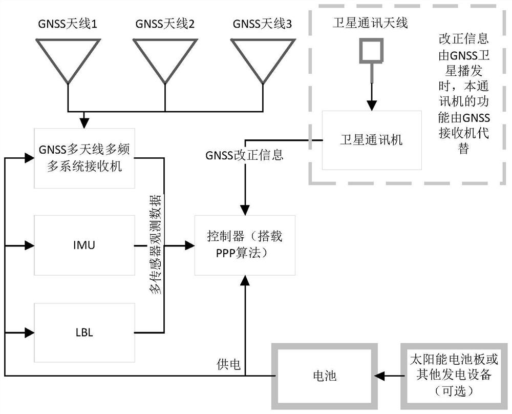
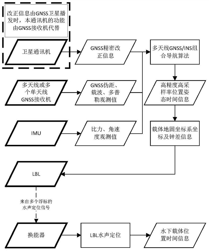
[0032] combine figure 1 , an underwater acoustic positioning and timing buoy, comprising a multi-antenna GNSS receiver, an inertial measurement unit, an underwater acoustic positioning device, a satellite communication machine, an underwater acoustic communication device, a battery and a controller, and the multi-antenna GNSS receiver is a single multi-antenna GNSS receiver or multiple single-antenna GNSS receivers.

[0033] The multi-antenna GNSS receiver is used to measure the precise coordinates of the main antenna and the coordinate increment value of each antenna relative to the main antenna, and obtain the coordinates of the buoy's ground-fixed coordinate system and the attitude information of the buoy;

[0034] The inertial measurement unit is used to measure the angular velocity and acceleration information of the ...


PUM


Abstract

The invention discloses an underwater acoustic positioning and timing buoy and an underwater positioning method, and relates to the field of underwater acoustic positioning. The buoy includes a multi-antenna GNSS receiver, an inertial measurement unit, underwater acoustic positioning equipment, a satellite communication device, an underwater acoustic communication device, a battery and a controller; the multi-antenna GNSS receiver is used to measure the precise coordinates of the main antenna and each antenna relative to the main antenna. The coordinate increment value of the antenna is used to obtain the coordinates of the ground-fixed coordinate system of the buoy and the attitude information of the buoy; the inertial measurement unit is used to measure the angular velocity and acceleration information of the buoy, and according to a group of initial position, velocity and attitude information of the buoy, additional The position, velocity and attitude at any time after the continuous calculation of the error; the underwater acoustic positioning equipment is used to transmit continuous acoustic signals underwater, and the underwater carrier receives the acoustic signals and measures the signal propagation time relative to the LBL equipment; satellite communication The machine is used to obtain real-time precise correction information from satellites; the controller is used to receive data, locate, send results and control other equipment.

Description

technical field [0001] The invention relates to the field of underwater acoustic positioning, in particular to an underwater acoustic positioning and timing buoy and an underwater positioning method. Background technique [0002] Position information and time information are necessary basic information for marine scientific research, seabed resource exploration, marine structure construction, marine intelligence network construction, etc. The availability, accuracy and economy of marine positioning, navigation and timing determine the high-level marine science. The regular conduct or construction of research, high-yield ocean investments, and high-quality ocean intelligence networks. [0003] For the positioning, navigation and timing of general carriers above the sea surface, GNSS technologies such as GPS and Beidou can usually be used to achieve, and the accuracy, usability and concealment of positioning, navigation and timing are better. However, there has been a lack of...

Claims


Application Information

Patent Timeline
Patent Type & Authority Patents(China)
IPC IPC(8): G01S19/47G01S19/33G01S5/22G01C21/16
CPCG01C21/165G01S5/22G01S19/33G01S19/47
Inventor 王胜利郑衍宁周兴华胡亮亮
Owner SHANDONG UNIV OF SCI & TECH
Why Eureka
Try Eureka